Audi A6 Typ 4G: Wheel Bearing Housing, Removing and Installing
Special tools and workshop equipment required
- Torque Wrench 1331 5-50Nm -VAG1331-
- Torque Wrench 1332 40-200Nm -VAG1332-
- Torque Wrench 1332 Insert - Ring Wrench - 21mm -VAG1332/7-
Removing
- Loosen the connection between the drive axle and wheel hub. Refer to → Chapter "Drive Axle Threaded Connection, Loosening and Tightening".
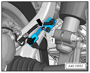
- Remove the bolt -arrow- and remove the bracket -1- brake line and electric wires from the wheel bearing housing.
- Remove the Front ABS Wheel Speed Sensor. Refer to → Break System; Rep. Gr.45.
- Remove the brake rotor and the brake caliper. Refer to → Brake System; Rep. Gr.46.
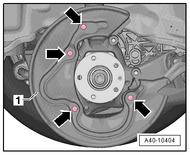
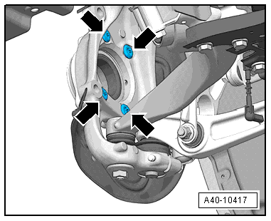
- Remove the bolts -arrows- and remove the brake shield -1-.
- Remove the control arm. Refer to → Chapter "Control Arm, Removing and Installing".
- Remove the nut from the guide link joint pins enough so it is flush with the joint pin threads. Counterhold when loosening.
To Protect Thread, Screw Nut On Pin A Few Turns.
- Press the guide link joint pin off the conical seat using the Puller - Ball Joint -T40042-.
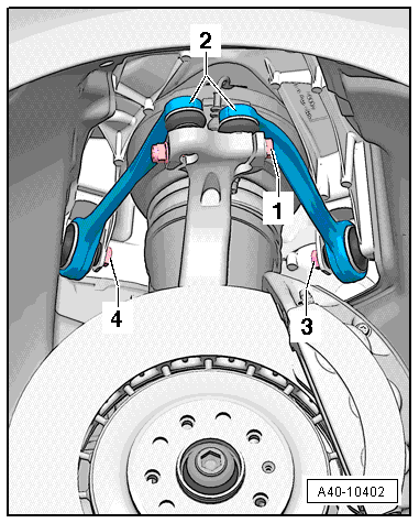
- Disconnect the threaded connection -1-.
- Remove booth joint pins in the upper control arm -2- from the wheel bearing housing.
The slits in the wheel bearing housing must not be widened using a chisel or similar tool!
- Loosen the wheel bearing housing from the drive axle splines and remove it.
 Note
Note
- The drive axle must not hang down, otherwise the inner joint will be damaged by over flexing.
- Secure drive axle to body using wire.
Installing
Install in reverse order of removal. Note the following:
- Slide the wheel bearing housing onto the drive axle splines.
- Insert both of upper control arm joint pins -2- in the wheel bearing housing and insert the bolt -1-.
- Remove the adhesive residue on the ball joint and guide link stub threads.
- Install the guide link on the wheel bearing housing and tighten.
- Install the control arm. Refer to → Chapter "Control Arm, Removing and Installing".
Note
Push the upper control arms -2- down as far as possible while tightening the bolts!
- Tighten the bolting -1-.
- Install the brake rotor and the brake caliper. Refer to → Brake System; Rep. Gr.46.
- Tighten the drive axle to wheel hub threaded connection. Refer to → Chapter "Drive Axle Threaded Connection, Loosening and Tightening".
- On vehicles with automatic head lamp range control, perform headlamp basic setting. Refer to → Electrical Equipment; Rep. Gr.94; Headlamp; Headlamp, Adjusting.
- If the Level Control Sensor was removed and installed or if the linkage was loosened, the control position must be programmed again by starting the correct program on the Vehicle Diagnostic Tester in Guided Functions.
- If the control position was reprogrammed on vehicles with lane assist, the Camera Control Module -J852- must be calibrated again. Refer to → Chapter "Driver Assistance Systems Front Camera, Calibrating".
- Install the wheel. Refer to → Chapter "Wheels and Tires".
- To determine if an axle alignment is required, see Table. Refer to → Chapter "Evaluating Need for Axle Alignment".
Wheel Bearing Unit, Removing and Installing
Special tools and workshop equipment required
- Torque Wrench 1331 5-50Nm -VAG1331-
- Torque Wrench 1332 40-200Nm -VAG1332-
- Torque Wrench 80-400Nm -VAG1576-
Removing
- Remove drive axle. Refer to → Chapter "Drive Axle, Removing and Installing".
- Remove the brake rotor and the brake caliper. Refer to → Brake System; Rep. Gr.46.
- Remove the Front ABS Wheel Speed Sensors-G45-/-G47-. Refer to → Break System; Rep. Gr.45.
- Remove the cap bolts -arrows-.
- Remove wheel bearing unit.
 Caution
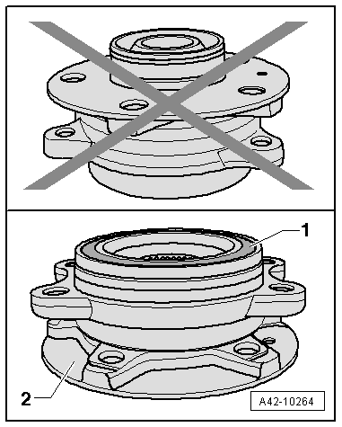
Avoid contaminating with dirt and damaging the seal when lifting, setting down/storing.
- The wheel bearing -1- must always face up.
- Always set the wheel bearing unit down on the wheel hub -2-.
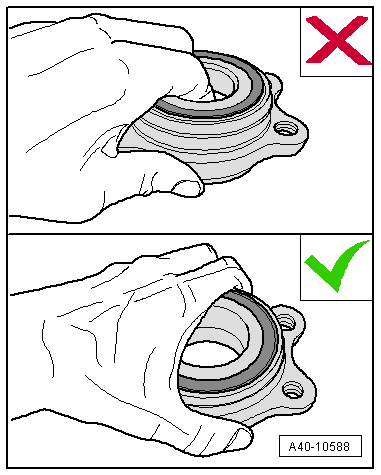
- Never reach into the inside when lifting the wheel bearing.
- Hold the wheel bearing only on the outside.
- Service the wheel bearing unit. Refer to → Chapter "Wheel Bearing Unit, Servicing".
Installing
Install in reverse order of removal. Note the following:
- Install the drive axle. Refer to → Chapter "Drive Axle, Removing and Installing".
- Install the wheel. Refer to → Chapter "Wheels and Tires".
- On vehicles with automatic head lamp range control, perform headlamp basic setting. Refer to → Electrical Equipment; Rep. Gr.94; Headlamp; Headlamp, Adjusting.
- If the Level Control Sensor was removed and installed or if the linkage was loosened, the control position must be programmed again by starting the correct program on the Vehicle Diagnostic Tester in Guided Functions.
- If the control position was reprogrammed on vehicles with lane assist, the Camera Control Module -J852- must be calibrated again. Refer to → Chapter "Driver Assistance Systems Front Camera, Calibrating".
Wheel Bearing Unit, Servicing
Special tools and workshop equipment required
- Shop Press -VAG1290A-
- Press Plate -VW401-
- Press Plate -VW402-
- Press Piece - Multiple Use -VW412-
- Hydraulic Press - Bushing Assembly Tool Kit -T10230-
- -3-Puller - Kukko Separating Tool - Diameter 25-155mm with Puller - Kukko Quick Action Separating Tool - 25-155mm -15/3 with 17/3-
Procedure
- Wheel bearing housing is removed. Refer to → Chapter "Wheel Bearing Unit, Removing and Installing".
Wheel Hub, Removing from Wheel Bearing
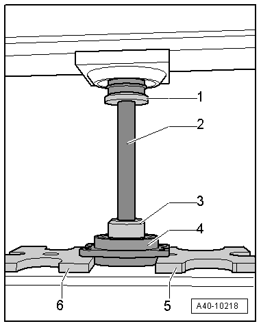
- Install special tools as shown in illustration.
1 - Press Piece - Multiple Use -VW412-
2 - Sleeve -T10230/3- from the Hydraulic Press - Bushing Assembly Tool Kit -T10230-
3 - Thrust Piece -T10230/8- from the Hydraulic Press - Bushing Assembly Tool Kit -T10230-
4 - Wheel bearing unit
5 - Press Plate -VW402-
6 - Press Plate -VW401-
- Press the wheel hub out of the wheel bearing.
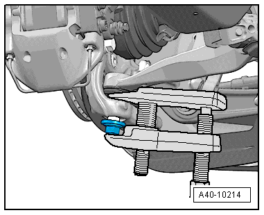
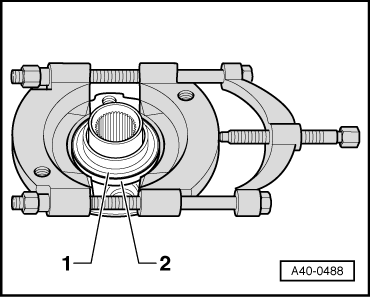
Removing the Bearing Inner Race from the Hub
- Insert the separating tool between the bearing inner race -1- and the wheel hub -2- and pretension with the spindle.
Note
Use a commercially available separating tool such as the Puller - Kukko Separating Tool - Diameter 25-155mm with Puller - Kukko Quick Action Separating Tool - 25-155mm -15/3 with 17/3-.
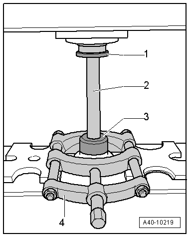
- Install special tools as shown in illustration.
1 - Press Piece - Multiple Use -VW412-
2 - Sleeve -T10230/3- from the Hydraulic Press - Bushing Assembly Tool Kit -T10230-
3 - Thrust Piece -T10230/8- from the Hydraulic Press - Bushing Assembly Tool Kit -T10230-
4 - Puller - Kukko Separating Tool - Diameter 25-155mm with Puller - Kukko Quick Action Separating Tool - 25-155mm -15/3 with 17/3-
- Press the bearing inner race from the hub.
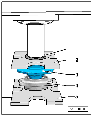
Pressing Wheel Hub Into Wheel Bearing
- Install special tools as shown in illustration.
1 - Press Piece - Multiple Use -VW412-
2 - Press Plate -VW402-
3 - Wheel hub
4 - Ball Bearing
5 - Press Plate -VW401-
Note
The reworked surface on the wheel bearing outer race faces down.
Caution
When setting down or pressing in, make sure there is no dirt or contaminants between the Press Plate -VW401--5- and the ball bearing -4-.
- Press the wheel hub into the wheel bearing.
- Install the wheel bearing unit. Refer to → Chapter "Wheel Bearing Unit, Removing and Installing".