Audi A6 Typ 4G: Electrical Component Locations Overview
 Note
Note
- The air lines leading to the air springs/air spring shock absorbers are tied inside the wiring harness.
- Air lines, servicing. Refer to → Chapter "Air Line, Servicing".
- Connecting piece, replacing. Refer to → Chapter "Connecting Piece, Replacing".
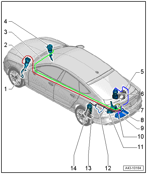
1 - Left Front Air Spring Shock Absorber
2 - "Red" Air Line
- From the solenoid valve block to the left front air shock absorber
- Front air line routing. Refer to → Fig. "Routing: Air Line to the Front Air Spring Damper"
3 - "Green" Air Line
- From the solenoid valve block to the right front air spring shock absorber
- Front air line routing. Refer to → Fig. "Routing: Air Line to the Front Air Spring Damper"
4 - Right Front Air Spring Shock Absorber
5 - "Blue" Air Line
- From solenoid valve block to rear right air spring
- Left rear air line routing. Refer to → Fig. "Air Line Routing to the Left Rear Air Spring"
- Right rear air line routing.
6 - Rear Right Air Spring
7 - Air Line "Brown"
- From air supply unit to solenoid valve block
- Air line, routing to solenoid valve block. Refer to → Fig. "Routing: Air Line from the Air Supply Unit to the Outer Solenoid Valve"
8 - Solenoid Valve Block
- Line arrangement on solenoid valve block. Refer to → Fig. "Solenoid Valve Block, Line Arrangement"
9 - Pressure Reservoir
10 - "Purple" Air Line
- From solenoid valve block to pressure reservoir
- Air line routing. Refer to → Fig. "Routing: Air Line from the Air Supply Unit to the Valve Block"
11 - Air Supply Unit
12 - Air Intake Line with Filter and Muffler
- Removing and installing. Refer to → Chapter "Intake Line with Filter, Removing and Installing".
13 - "Black" Air Line
- From solenoid valve block to rear left air spring
- Rear air line routing. Refer to → Fig. "Air Line Routing to the Left Rear Air Spring"
14 - Rear Left Air Spring
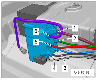
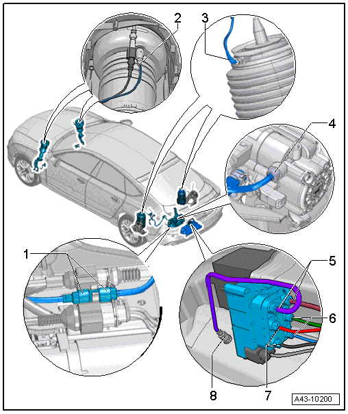
Solenoid Valve Block, Line Arrangement
Note
The air lines are tied inside the wiring harness in front of the opening to the vehicle interior.
Air pipes are color-coded:
1 - "Brown" air line: from the air supply unit
2 - "Green" air line: to the right front air spring shock absorber
3 - "Blue" air line: to the right rear air spring
4 - "Black" air line: to the left rear air spring
5 - "Red" air line: to the left front air spring shock absorber
6 - "Purple" air line: to the pressure reservoir
For servicing the air line separating point.
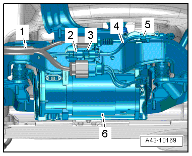
Routing: Air Line from the Air Supply Unit to the Outer Solenoid Valve
The air line -4- runs from the air supply unit -6- to the solenoid valve block and is tied into the wiring harness -1-.
2 - Wiring connector end piece
3 - Bracket
5 - Clip
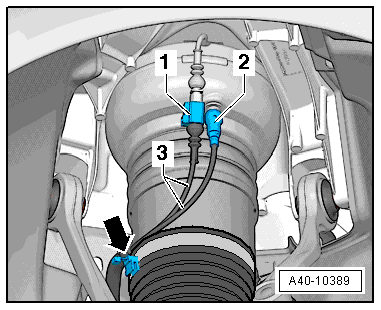
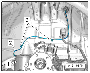
Routing: Air Line to the Front Air Spring Damper
The clip -arrow- holds the air line in the wiring harness.
- Do not loosen the residual pressure retaining valve -2-.
For servicing the air line separating point.
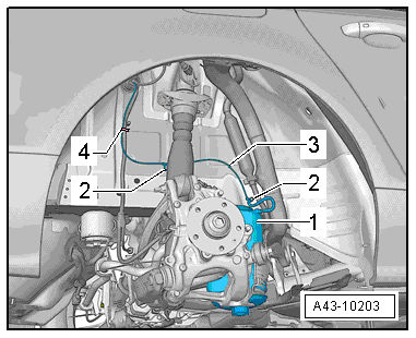
Air Line Routing to the Left Rear Air Spring
1 - Rear air spring
2 - Air line
3 - Clip
Air Line Routing to the Right Rear Air Spring
1 - Rear air spring
2 - Clip
3 - Air line
4 - Cable Tie
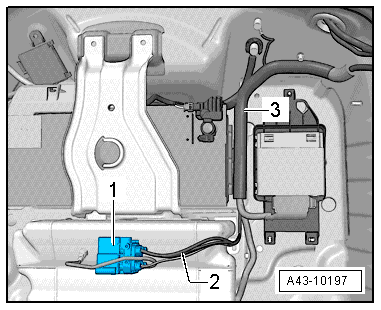
Routing: Air Line from the Air Supply Unit to the Valve Block
The air line -2- runs to the solenoid valve block -1- and it attached in the wiring harness -3-.
Overview - Air Supply Unit
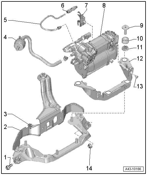
1 - Bolt
- 9 Nm
2 - Bracket
- Entire air supply unit to spare wheel well
- Removing and installing. Refer to → Chapter "Air Supply Unit with Bracket, Removing and Installing".
3 - Clip
4 - Intake Line with Filter
- Removing and installing. Refer to → Chapter "Intake Line with Filter, Removing and Installing".
5 - Air Line
- Between solenoid valve block and air supply unit
- Air lines overview -Item 7-
- For the air line connecting piece tightening specification. Refer to → Chapter "Overview - Air Lines".
6 - Line Connector
7 - Bracket
8 - Air Supply Unit with Level Control System Solenoid -N111-
- Removing and installing. Refer to → Chapter "Air Supply Unit, Removing and Installing".
- Level Control System Solenoid -N111-, Removing and Installing. Refer to → Chapter "Level Control System Solenoid -N111-, Removing and Installing".
- If the air supply unit was replaced, then the Level Control System Compressor Relay -J403- must also be replaced. Installed location. Refer to → Wiring diagrams, Troubleshooting & Component locations.
9 - Threaded Sleeve
- 7.5 Nm
- Quantity: 4
10 - Spring
- Quantity: 4
11 - Rubber Bushing
- Quantity: 4
12 - Bracket
13 - Bolt
- 9 Nm
- Air supply unit to retainer
- Quantity: 3
14 - Nut
- 9 Nm
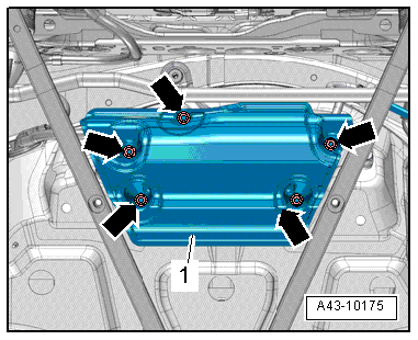
Stone Chip Protection Tightening Specification
- Tighten the nuts -arrows- to 9 Nm.
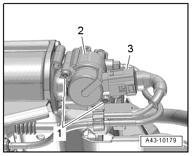
Level Control System Solenoid -N111- Tightening Specification
Tighten the bolts -1- to 5 Nm.
Overview - Air Lines
Air Lines
1 - Line Connector
2 - Front Air Spring Shock Absorber Connecting Piece
- 3 Nm
3 - Rear Air Spring Connecting Piece
- 2.5 Nm
4 - Air Supply Unit Connecting Piece
- 3 Nm
5 - Solenoid Valve Connecting Pieces
- 3.5 Nm
- Quantity: 2, 12 mm
6 - Solenoid Valve Connecting Pieces
- Quantity: 2, 10 mm
- 2 Nm
7 - Solenoid Valve Connecting Pieces
- 3.5 Nm
- Quantity: 2, 12 mm
8 - Pressure Reservoir Connecting Piece
- 5 Nm
Separating Points
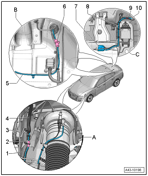
A - Separating Point: Air Line for the Front Air Spring Shock Absorber
1 - New Air Line
2 - Bonded Wiring Connector
3 - Original Air Line
4 - Wiring Harness
B - Separating Point: Air Line for the Rear Air Spring
5 - New Air Line
6 - Bonded Wiring Connector
C - Separating Point: Air Line for the Solenoid Valve Block Inside the Vehicle
7 - New Air Line
8 - Wiring Harness
9 - Bonded Wiring Connector
10 - Original Air Line
