Audi A6 Typ 4G: Bracket, Removing and Installing
 Caution
There is a risk of malfunctions.
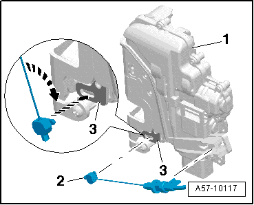
The door lock must be removed and installed together with the bracket to prevent over-bending the cable when disengaging and engaging it.
The cable must be disconnected from/attached to the lever on the door lock outside of the door.
Special tools and workshop equipment required
- Pry Lever -80-200 -
Removing
- Remove the door trim panel. Refer to → Body Interior; Rep. Gr.70; Rear Door Trim Panels; Rear Door Trim Panel, Removing and Installing.
- Remove the inner door panel cover. Refer to → Chapter "Door Inner Cover, Removing and Installing".
- Remove the outside door handle. Refer to → Chapter "Exterior Door Handle, Removing and Installing".
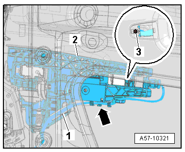
- Disengage the electrical wire on the mounting bracket -arrow- if applicable.
- Free up the spiral clip -1- from the wire using the Pry Lever -80 - 200-.
 Note
Note
Use a soapy solution if necessary make removal easier.
- Remove the bolt -3- and the mounting bracket -2-.
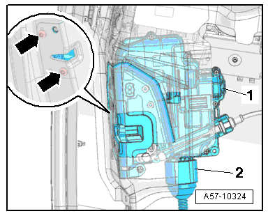
- Remove the bolts -arrows- from the door lock.
- Disconnect the connector -2-.
- Push the bracket and door lock -1- downward and remove them from the vehicle.
- If the bracket is to be replaced, also remove the following components:
- Remove the door lock cable. Refer to → Chapter "Door Lock Cable, Removing and Installing".
Installing
Install in reverse order of removal.
Door Lock, Removing and Installing
Door Lock, Removing and Installing
 Caution
There is a risk of malfunctions.
The door lock must be removed and installed together with the bracket to prevent over-bending the cable when disengaging and engaging it.
The cable must be disconnected from/attached to the lever on the door lock outside of the door.
Removing
- Remove the door trim panel. Refer to → Body Interior; Rep. Gr.70; Rear Door Trim Panels; Rear Door Trim Panel, Removing and Installing.
- Remove the inner door panel cover. Refer to → Chapter "Door Inner Cover, Removing and Installing".
- Remove the outside door handle. Refer to → Chapter "Exterior Door Handle, Removing and Installing".
- Disengage the electrical wire on the mounting bracket -arrow- if applicable.
- Free up the spiral clip -1- from the wire using the Pry Lever -80 - 200-.
 Note
Note
Use a soapy solution if necessary make removal easier.
- Remove the bolt -3- and the mounting bracket -2-.

- Remove the bolts -arrows- from the door lock.
- Disconnect the connector -2-.
- Push the bracket and door lock -1- downward and remove them from the vehicle.
- If the bracket is to be replaced, also remove the following components:
- Remove the door lock cable. Refer to → Chapter "Door Lock Cable, Removing and Installing".
Installing
Install in reverse order of removal.

Door Lock Cable, Removing and Installing
 Caution
There is a risk of malfunctions.
The door lock must be removed and installed together with the bracket to prevent over-bending the cable when disengaging and engaging it.
The cable must be disconnected from/attached to the lever on the door lock outside of the door.
Removing
- Remove the bracket and the door lock. Refer to → Chapter "Door Lock, Removing and Installing".
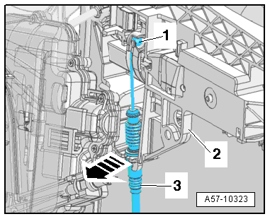
- Turn the operating cable on the lever -1- 90º in the direction of -arrow A- and remove it from the cable bracket -2-.
- Rotate the cable on the door lock release lever -3- in the direction of -arrow B-.
- The cable must be aligned with the opening on the release lever.
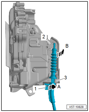
- Disengage the operating cable -1- on the operating lever by pressing the cable bracket -3- out of the mount on the mounting bracket -2--arrow-.
- Remove the operating shaft.
Installing
Install in reverse order of removal.
Operating Cable for Interior Door Mechanism, Removing and Installing
 Caution
There is a risk of malfunctions.
When removing and installing, make sure the actuating link is not kinked or damaged.
Removing
- Remove the housing. Refer to → Chapter "Housing, Removing and Installing".
- Remove the inner door panel cover. Refer to → Chapter "Door Inner Cover, Removing and Installing".
- Remove the bolts -arrows-.
- Move the door lock -1- to the side.
- Disconnect the connector -2-, if necessary.

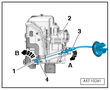
- Disengage the actuating link -3- at the door lock cable bracket -2--arrow A-.
- Turn the nipple -1- 90º in direction of -arrow B- and remove it from the release lever -4- for the interior door mechanism.
Installing
Install in reverse order of removal. Note the following:
- Insert the nipple -2- into the release lever -3- for the interior door mechanism -lower arrow-.
- Rotate the nipple 90º -top arrow- and press the actuating link into the cable bracket on the door lock -1- until it engages audibly.
