Audi A6 Typ 4G: Driver Side Instrument Panel Cover, Removing and Installing
Driver Side Instrument Panel Cover, Removing and Installing
Special tools and workshop equipment required
- Wedge Set -T10383-
Removing
- Remove the driver side instrument panel side cover. Refer to → Chapter "Instrument Panel Side Cover, Removing and Installing".
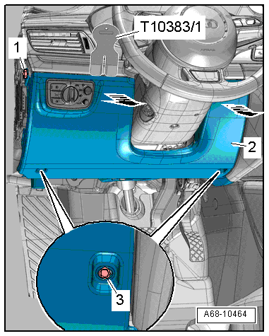
- Remove the side bolt -1-.
- Remove the lower bolts -3-.
- Unclip the driver side instrument panel cover -2- from the instrument panel starting from the upper edge using the Wedge Set -T10383/1--arrows-.
 Note
Note
The instrument panel cover can only be unclipped from the instrument panel by exerting a relatively high amount of force.
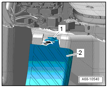
- Remove the instrument panel lower cover from the tab on the foot rest.
- Disconnect the connector from the light switch.
- Unclip the 16-Pin Connector -T16- (Data Link Connector).
- If the vehicle has footwell lamps: disconnect the connector.
Installing
Install in reverse order of removal. Note the following:
- Insert the bottom instrument panel cover -1- into the clip -2- on the foot rest -arrow-.
Installation notes, for example tightening specifications, replacing components. Refer to → Chapter "Overview - Driver Side Instrument Panel Cover".
Front Footwell Cover, Removing and Installing
Special tools and workshop equipment required
- Trim Removal Wedge -3409-
Removing
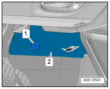
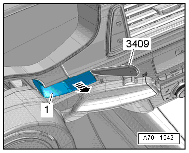
- Pry off the cap -1- with a screwdriver and remove the bolt underneath it.
- Unclip the cover -2- using the Trim Removal Wedge -3409--arrow-.
- Pull the cover downward and remove it.
Installing
Install in reverse order of removal.
Installation notes, for example tightening specifications, replacing components. Refer to → Chapter "Overview - Driver Side Instrument Panel Cover".
Instrument Cluster Gap Cover, Removing and Installing
Special tools and workshop equipment required
- Trim Removal Wedge -3409-
Removing
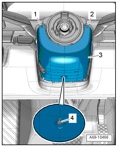
- Move the steering wheel as far down as possible.
- Unclip the gap cover -1- using the Trim Removal Wedge -3409--arrow- and remove it.
- Repeat the process on the opposite side of the gap cover.
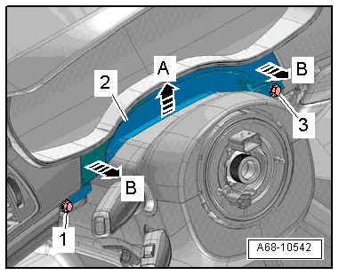
- Remove the bolts -1 and 3-.
- Using a small flat-head screwdriver, carefully unclip the gap cover -2- from the upper trim panel for the steering column switch module -arrow A-.
- Unclip the instrument cluster gap cover from the instrument panel using the Trim Removal Wedge -3409--B arrows-.
- Remove the cover.
Installing
Installation is performed in the reverse of removal, but note the following:
Installation notes, for example tightening specifications, replacing components. Refer to → Chapter "Overview - Steering Column Trim Panel".
Upper Steering Column Trim Panel, Removing and Installing
Removing
- Move the steering wheel as far down as possible.
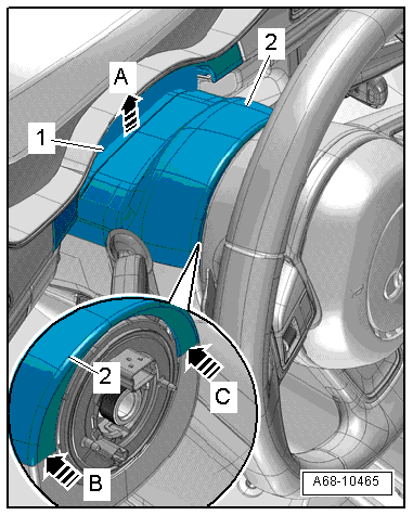
- Using a small flat-head screwdriver, carefully unclip the gap cover -1- from the upper trim panel -2- for the steering column switch module in direction of -arrow A-.
- Turn the steering wheel counterclockwise 90º from the straight position.
- Carefully pry the upper trim off the lower trim using a small flat blade screwdriver in direction of -arrow B-.
- Turn the steering wheel back 180º and repeat the procedure on the opposite side in direction of -arrow C-.
- Disengage the upper steering column switch module trim from the lower trim and remove it.
Installing
Install in reverse order of removal. Note the following:
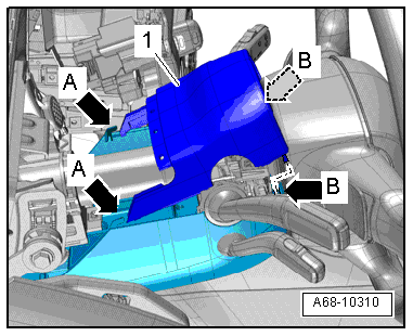
- Engage the upper trim panel -1- in the lower trim panel -A arrows-.
- Make sure that the lower trim panel pins engage in the opening at the upper trim panel retaining tab -B arrows-.
Installation notes, for example tightening specifications, replacing components. Refer to → Chapter "Overview - Steering Column Trim Panel".
Lower Steering Column Trim Panel, Removing and Installing
Removing
Note
For reasons of clarity, the steering wheel is not shown.
- Remove the upper steering column switch module trim. Refer to → Chapter "Upper Steering Column Trim Panel, Removing and Installing".
- Turn the steering wheel counterclockwise 90º from the straight position.
- Remove the bolt -1-.
- Turn steering wheel back 180º and remove screw -2- on the opposite side.
Note
When the bolts -1 and 2- are not accessible, the steering wheel must be removed for further work. Refer to → Suspension, Wheels, Steering; Rep. Gr.48; Steering Wheel; Steering Wheel, Removing and Installing.
- Remove screw -4- and lower steering column switch module trim -3-.
- Disconnect the connector and unclip the cable holder.
Installing
Install in reverse order of removal. Note the following:
Installation notes, for example tightening specifications, replacing components. Refer to → Chapter "Overview - Steering Column Trim Panel".