Audi A6 Typ 4G: Level Control System Control Module -J197-, Removing and Installing
The Level Control System Control Module -J197- is behind the luggage compartment side trim panel on the right side.
Removing
- If the control module is being replaced, then select "replace" control module on the Vehicle Diagnostic Tester in Guided Functions.
- Follow the prompts on the screen.
- Turn off the ignition and remove the key.
- Remove the right luggage compartment side trim panel. Refer to → Body Interior; Rep. Gr.70; Luggage Compartment Trim Panels; Luggage Compartment Side Trim Panel, Removing and Installing.
- Remove the relay and fuse panel. Refer to → Electrical Equipment; Rep. Gr.97; Relay Carriers, Fuse Panels and E-Boxes; Relay and Fuse Panels In Luggage Compartment on Right Side, Removing and Installing.
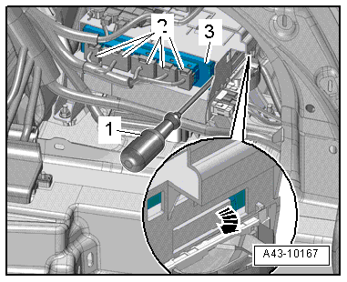
- Disconnect the connectors -2-.
- Open the releases on the left and right side with a long screwdriver -1--arrow- and remove the Level Control System Control Module -J197--3-.
Installing
Install in reverse order of removal. Note the following:
- Adapt the control position. Refer to → Chapter "Control Position, Programming".
Air Line, Servicing
Special tools and workshop equipment required
- Torque Wrench 1783 - 2-10Nm -VAG1783-
- Torque Wrench 1783 - Open Jaw - 10mm -VAG1783/1-
- Hose Cutting Pliers -VAS6228-
Procedure
If the air line is damaged, the damaged area can be replaced.
If the connection leaks, air line can be shortened by 10 mm (0.39 in.) and a new connecting piece installed. Refer to → Chapter "Connecting Piece, Replacing".
 Note
Note
- The air line between the solenoid valve block and the pressure reservoir and between the solenoid valve block and the air supply unit are completely replaced by the original lines.
- Clean separation point area before disconnecting air line connector.
- Contaminants entering the lines can lead to system malfunction.
- Clean connector piece area and corresponding separation point.
For an overview on separating points.
- Cut through the air line at a right angle at the connector area using Hose Cutting Pliers -VAS6228-.
- Remove connector piece and air line.
- Then mark ends of air line in vehicle and both ends of new air line with a waterproof pen.
Note
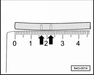
With 17 mm or 22 mm markings, check whether connector piece is inserted far enough in air line.
- Place foam rubber on both lines.
- Install new line connector.
Note
Connector pieces in line connector are already tightened to proper torque. Air lines only have to be connected.
- Remove transport protection cap.
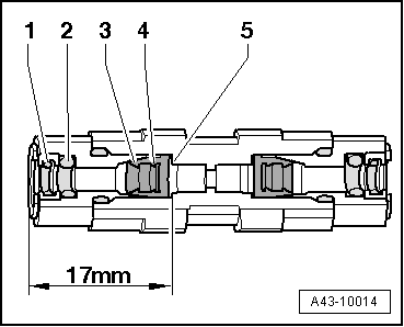
- Slide old air line through gaskets -1 and 2-.
- Then slide air line with some force through edges -3 and 4- of cutting rings as far as stop -5- in line connector.
- Slide the foam rubber onto the connector piece.
- Repeat procedure with new air line.
- Connecting piece, replacing. Refer to → Chapter "Connecting Piece, Replacing".
-Item A- Separating point: air line for the front air spring shock absorber.
- Loosen the original air line from the wiring harness.
- Surround the wiring harness properly.
- Service the air line.
- Attach the wiring connector and the new air line to the wiring harness with cable ties.
-Item B- Separating point: air line for the rear air spring.
Note
Route the new air line -Item 5- as illustrated.
- Service the air line.
- Attach the bonded wiring connector and the new air line with cable ties.
-Item C- Separating point: air line for the solenoid valve block inside the vehicle.
Note
If the air lines on the solenoid valve are damaged, then route the separating point inside the vehicle interior (spare wheel well) due to the short lines.
- Loosen the original air line from the wiring harness.
- Surround the wiring harness properly.
- Service the air line.
- Attach the wiring connector and the new air line to the wiring harness with cable ties.
Note
- The vehicle may be removed from the vehicle hoist only after the air springs have been filled again. Refer to → Chapter "Raising and Lowering with Open and Closed Air Suspension System".
- Make sure the positioning pin on the air spring is installed correctly inside the body before filling the air suspension system. The air spring must be locked secure inside the wheel bearing housing at the same time. Refer to → Fig. "Air Spring Installed Position".
Connecting Piece, Replacing
Special tools and workshop equipment required
- Torque Wrench 1783 - 2-10Nm -VAG1783-
- Torque Wrench 1783 - Open Jaw - 10mm -VAG1783/1-
- Hose Cutting Pliers -VAS6228-
If connector leaks, if air line is long enough, it can be shortened by 10 mm (0.39 in.) and a new connecting piece installed.
Note
- Clean separation point area before disconnecting air line connector.
- Contaminants entering the lines can lead to system malfunction.
- Clean connector piece area.
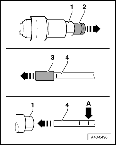
- Remove connector piece and air line.
- Remove cutting ring from air line.
- Using the Hose Cutting Pliers -VAS6228-, cut the air line behind pressure point from cutting ring at right angle.
- Then mark air line ends in vehicle with a waterproof pen.
Note
- With 17 mm or 22 mm markings, check whether connector piece is inserted far enough in air line.
- Always replace connector piece.
- Maintain the tightening specification.
- Install new connector piece by hand and tighten. Refer to → Chapter "Overview - Air Lines".
- Only remove transport protection caps -2 and 3- after connecting air line -4-.
- Route air line with appropriate clips/grommets in vehicle. Replace cut cable ties if necessary.
- Remove transport protection -2 and 3-.
- Slide air line -4- in with some force as far as stop in connector piece -1-.
- Air lines are installed correctly when only one of the two markings is visible -arrow A-.