Audi A6 Typ 4G: Drive Axle, Removing and Installing
Special tools and workshop equipment required
- Torque Wrench 1332 40-200Nm -VAG1332-
- Torque Wrench 80-400Nm -VAG1576-
Removing
- Loosen the connection between the drive axle and wheel hub. Refer to → Chapter "Drive Axle Threaded Connection, Loosening and Tightening".
- Remove the wheel. Refer to → Chapter "Wheels and Tires".
- Remove the rear noise insulation. Refer to → Body Exterior; Rep. Gr.66; Noise Insulation; Noise Insulation, Removing and Installing.
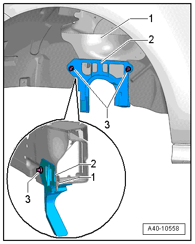
- Remove the nuts -3- and remove the cover -2- (if equipped) from the right and left drive axle.
- Tip the top of the cover -2- toward the outside and guide it downward by the seam -1-.
- Remove both heat shields from the subframe. Refer to → Chapter "Subframe Heatshield, Removing and Installing".
- Move the auxiliary water pump (if equipped) with the lines still connected to the side.
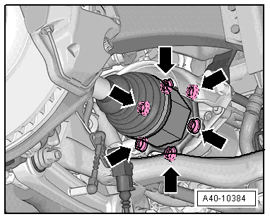
- Remove the bolts -arrows- from the flange shaft/transmission.
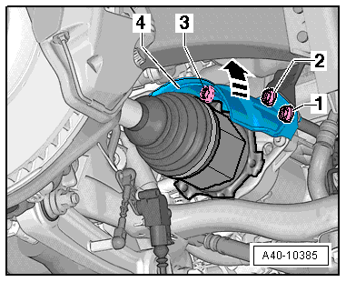
- Remove the bolts -1, 2 and 3- and remove the heat shield -4-.
- Turn the wheel bearing housing as far toward the inside as possible.
- Remove the drive axle.
 Note
Note
- Be careful not to damage the dust boot when removing the drive axle.
- Ignore -arrow-.
Installing
Install in reverse order of removal. Note the following:
- Install the wheel. Refer to → Chapter "Wheels and Tires".
Drive Axle Threaded Connection, Loosening and Tightening
Special tools and workshop equipment required
- Torque Wrench 80-400Nm -VAG1576-
Loosen the Threaded Connection Between the Drive Axle and Wheel Hub
- With vehicle still standing on its wheels, loosen bolt a maximum of 90º, otherwise wheel bearing will be pre-damaged.
- Lift the vehicle just enough so that the wheels are hanging free.
- Apply the brakes (a second technician required).
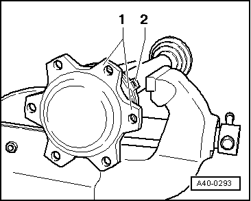
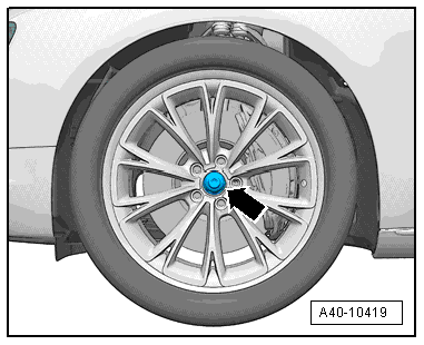
- Remove the bolt -arrow-.
Tighten the Threaded Connection Between the Drive Axle and Wheel Hub
- Replace the bolt -arrow-.
Note
- Before installing, clean the threads in the CV joint with a tap.
- Wheels must not yet touch the ground to tighten the drive axle, wheel bearing may otherwise be damaged.
- Apply the brakes (a second technician required).
- Tighten bolt to 200 Nm.
- Lower the vehicle onto its wheels.
- Tighten bolt an additional 180º.
Drive Axle, Disassembling and Assembling
Special tools and workshop equipment required
- Press Plate -VW401-
- Press Plate -VW402-
- Press Piece - Rod -VW408A-
- Press Piece - Rod -VW411-
- Press Piece - 37mm -VW416B-
- Press Piece - Multiple Use -VW447H-
- Torque Wrench 1331 5-50Nm -VAG1331-
- Torque Wrench 1332 40-200Nm -VAG1332-
- Clamping Pliers -VAG1682A-
- Tripod Joint Tool -T10065-
- Slide Hammer Set -VW771-
- Triple Roller Assembly Tool -T40018- for triple roller joint AAR 3300 i
Triple Roller Joint AAR 3300 i, Disassembling
- Clamp drive axle horizontally in vise.
Note
- Use vise clamp jaw protectors.
- Make sure that drive axle is not damaged.
- Mark the location of the joint to the drive axle
If they are not marked and are not installed in their previously installed positions, noises may occur later during driving operation.
A water-proof felt pen is well-suited for marking.
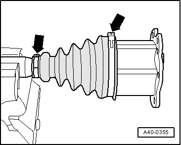
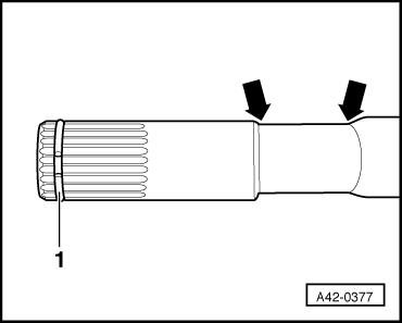
- Open clamps -arrows-.
- Slide back protective boot.
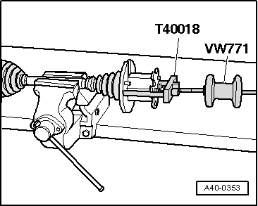
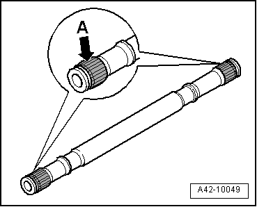
Allocate the Assembly/Removal Tool for Removing the Joint.
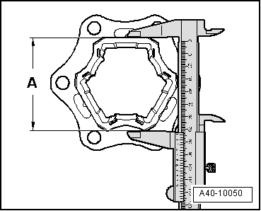
- Determine dimension -A- as shown in illustration.
- Dimension -A- approximately 76 mm = drive axle with triple roller joint AAR 3300 i, use Triple Roller Assembly Tool -T40018-
 Caution
Make sure that correct special tool allocation for each drive axle.
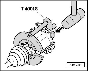
- Guide in the Triple Roller Assembly Tool -T40018- for the triple roller joint AAR 3300 i behind the joint.
- Guide pins -1- must contact joint.
- Move the Triple Roller Assembly Tool -T40018- up against the joint by turning knurled screws -2-.
Note
- Secure the joint without play in the Triple Roller Assembly Tool -T40018-.
- Tighten the screws -2- only by hand.
- Install the Slide Hammer Set -VW771- in the Triple Roller Assembly Tool -T40018-.
- Pull joint out horizontally with impact tool.
- Leave the joint in the Triple Roller Assembly Tool -T40018-.
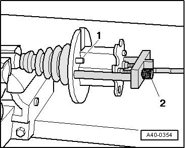
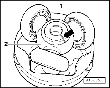
- Mark installation position of the parts -1 and 2- with lines.
If they are not marked and are not installed in their previously installed positions, noises may occur later during driving operation.
A water-proof felt pen is well-suited for marking.
1 - Drive axle
2 - Triple roller star
- Remove grease with lint-free cloth.
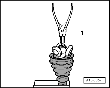
- Remove the circlip.
1 - Pliers (commercially available)
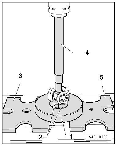
Press Triple Roller Star Off of Drive Axle
- Use special tool shown in illustration.
1 - Assembly Tool -T10065/1-
2 - Triple Roller Assembly Tool -T10065/5- - must touch the triple roller star base
3 - Press Plate -VW401-
4 - Press Piece - Rod -VW408A-
5 - Press Plate -VW402-
- The Triple Roller Assembly Tool -T10065/5- must not touch the rollers; move the rollers to the side if necessary.
- Pressing triple roller star off of drive axle.
- Remove the protective boot.
- Remove the grease on the shaft splines.
- Check the roller body and ball cage for wear.
- Clean drive axle and housing.
Triple Roller Joint AAR 3300 i, Assembling
- Slide on the small clamp with the CV boot and position the CV boot on the drive axle
- Position protective joint boot between -arrows-.
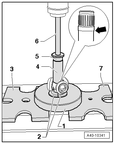
Tripod Roller Star, Pressing Onto Drive Axle
- Before installing joint or triple roller star, splines -A- must be lightly coated with grease used in joint.
- Place triple roller star on shaft according to marking and drive on until impact.
Use the Triple Roller Assembly Tool -T10065/6- and make sure it attaches to the bead at the bottom -arrow- in the drive axle.
- Use special tool shown in illustration.
1 - Assembly Tool -T10065/1-
2 - Triple Roller Assembly Tool -T10065/6- - must attach to the bead at the bottom of the drive axle -arrow-.
3 - Press Plate -VW401-
4 - Press Piece - 37mm -VW416B-
5 - Press Piece - Multiple Use -VW447H-
6 - Press Piece - Rod -VW411-
7 - Press Plate -VW402-
- The Triple Roller Assembly Tool -T10065/6- must not touch the roller; move the rollers to the side if necessary.
- Install circlip.
- Circlip must engage audibly, triple roller star must lie against circlip with no gap.
1 - Pliers (commercially available)
- Press 70 grams of joint grease, from repair kit, into the reverse side of the triple roller joint.
- Lightly grease the roller body.
- Press the joint over the triple roller star using a plastic hammer. Make sure roller body does not tilt!
- Press remaining quantity of grease in protective boot.
- Make sure the protective boot is seated on the joint correctly.
- Protective joint boot must fit in groove and on joint contour.
- Install clamp.
Note
For a better alignment of multi-point socket head bolts when installing drive axle, clamping sleeve connecting tube -2- must be between joint connecting flanges -1-.
- Install the clamps on the triple roller joint. Refer to → Chapter "Clamp on Triple Roller Joint and Outer Joint, Tensioning".