Audi A6 Typ 4G: Front Seat Control Module Bracket, Removing and Installing
Removing
- Remove the front seat control module:
- For the memory seat/steering column adjustment control module. Refer to → Chapter "Seat/Steering Column Adjustment Control Module with Memory Function, Removing and Installing".
- For the seat ventilation control module (integrated in the seat heating). Refer to → Chapter "Seat Ventilation Control Module (Integrated in Seat Heating), Removing and Installing".
- Passenger Occupant Detection System Control Module -J706- - market-specific. Refer to → Chapter "Passenger Occupant Detection System, Removing and Installing".
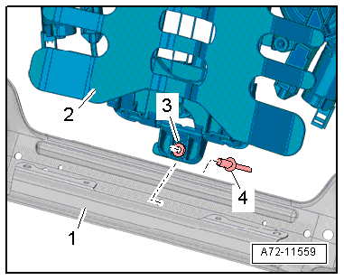
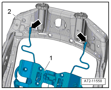
- Press the pin -2- out of the clip -arrow A- in the bracket -1- in the direction of the seat cushion using an upholstery needle, for example.
- Remove the pin that was pressed out from the seat pan.
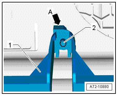
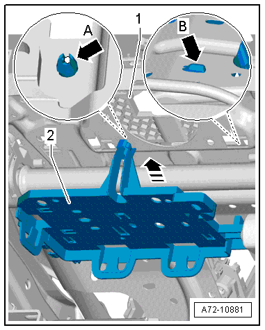
- Remove the support foot -2- from the upper frame of seat pan -1-, unclipping clip -arrow A- at the upper seat frame.
- Detach retaining tabs -arrow B- on both sides.
- Carefully remove bracket from the seat pan in direction of -arrow-.
Installing
Install in reverse order of removal. Note the following:
Installation notes, for example tightening specifications, replacing components. Refer to → Chapter "Overview - Seat Pan, Front Seat Control Module".
Seat Cushion Blower Fan, Removing and Installing, Standard Seat/Sport Seat/Super Sport Seat
Removing
 WARNING
- Follow all Safety Precautions when working with pyrotechnic components. Refer to → Chapter "Pyrotechnic Components Safety Precautions".
- Before handling pyrotechnic components (for example, disconnecting the connector), the person handling it must "discharge static electricity". This can be done by touching the door striker, for example.
- Remove the front seat. Refer to → Chapter "Front Seat, Removing and Installing".
- Fasten the front seat on the Engine/Transmission Holder - Seat Repair Fixture -VAS6136-. Refer to → Chapter "Front Seat, Mounting on Fixture for Seat Repair".
- Remove the backrest. Refer to → Chapter "Front Backrest, Removing and Installing, Standard Seat/Sport Seat/Super Sport Seat".
- Remove the padding from the lower seat frame. Refer to → Chapter "Lower Seat Frame Cover and Cushion, Removing and Installing, Standard Seat".
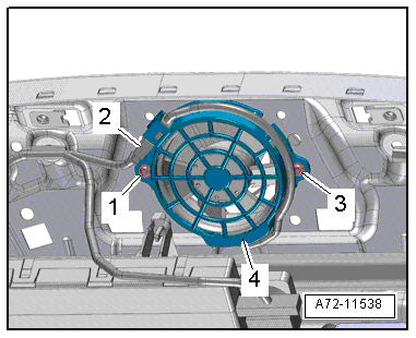
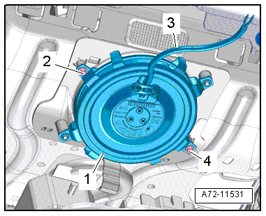
- Disconnect the connector -2- from the seat cushion fan and free up the electric wire.
- Remove the bolts -1 and 3-.
- Turn the cover grid -4- at little counter-clockwise and remove the fan.
Installing
WARNING
- Follow all Safety Precautions when working with pyrotechnic components. Refer to → Chapter "Pyrotechnic Components Safety Precautions".
- Before handling pyrotechnic components (for example, connecting the connector), the person handling it must "discharge static electricity". This can be done by touching the door striker, for example.
- Observe all measures when installing the front seat. Refer to → Chapter "Front Seat, Removing and Installing".
Install in reverse order of removal. Note the following:
- Set sealing ring for blower fan in place and install blower fan.
Installation notes, for example tightening specifications, replacing components. Refer to → Chapter "Overview - Seat Pan, Seat Cushion Blower Fans".
Seat Cushion Blower Fan, Removing and Installing, Multi-contour Seat
Removing
- Move the front seat all the way forward/up.
Seat Cushion Fan through 08/2012:
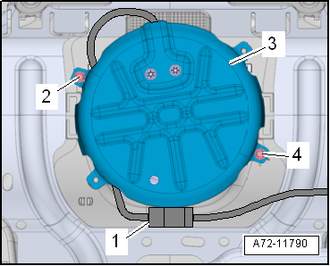
- Disconnect the connector from the seat cushion fan and free up the electric wire -3-.
- Remove the bolts -2-, -4- on the bracket and remove the seat cushion fan -1-.
Seat Cushion Fan from 09/2012:
- Remove the bolts -2 and 4- and then remove the cover -3- and the seat cushion blower fan.
- Disconnect the seat cushion blower fan connector -1-.
Installing
Install in reverse order of removal. Note the following:
- Set sealing ring for blower fan in place and install blower fan.
Installation notes, for example tightening specifications, replacing components. Refer to → Chapter "Overview - Seat Pan, Seat Cushion Blower Fans".
Seat Cushion Blower Fan Bracket, Removing and Installing, Multi-contour Seat
Removing
WARNING
- Follow all Safety Precautions when working with pyrotechnic components. Refer to → Chapter "Pyrotechnic Components Safety Precautions".
- Before handling pyrotechnic components (for example, disconnecting the connector), the person handling it must "discharge static electricity". This can be done by touching the door striker, for example.
- Remove the front seat. Refer to → Chapter "Front Seat, Removing and Installing".
- Fasten the front seat on the Engine/Transmission Holder - Seat Repair Fixture -VAS6136-. Refer to → Chapter "Front Seat, Mounting on Fixture for Seat Repair".
- Remove the backrest. Refer to → Chapter "Front Backrest, Removing and Installing, Multi-contour Seat".
- Remove the padding at the side and rear of the seat pan. Refer to → Chapter "Seat Pan Cover and Cushion, Removing and Installing, Multi-contour Seat".
- Remove the seat cushion fan. Refer to → Chapter "Seat Cushion Blower Fan, Removing and Installing, Multi-contour Seat".
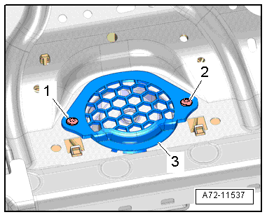
- Remove the bolts -1-, -2- and the fan grille -3-.
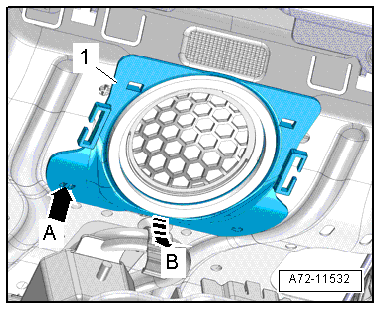
- Release the retainer -arrow A-.
- Move the bracket -1- downward -arrow B-, disengage is from the lower seat frame and remove it.
Installing
WARNING
- Follow all Safety Precautions when working with pyrotechnic components. Refer to → Chapter "Pyrotechnic Components Safety Precautions".
- Before handling pyrotechnic components (for example, connecting the connector), the person handling it must "discharge static electricity". This can be done by touching the door striker, for example.
- Observe all measures when installing the front seat. Refer to → Chapter "Front Seat, Removing and Installing".
Install in reverse order of removal. Note the following:
Installation notes, for example tightening specifications, replacing components. Refer to → Chapter "Overview - Seat Pan, Seat Cushion Blower Fans".
Safety Ground Lock, Removing and Installing
Removing
- Move the front seat all the way forward/up.
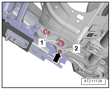
- Remove the bolts -1-.
- Disengage the retaining plate -2- on the lower seat frame -arrow- and remove.
 Caution
Risk of damage to the bushing in the bearing point (safety ground lock).
- The bushing cannot be replaced with workshop materials.
- If a bushing is damaged, the assembly part must be replaced.
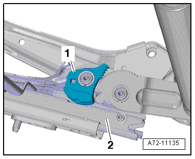
- Remove safety ground lock -1- from the mounting pin on the seat pan lower frame -2-.
Installing
Install in reverse order of removal. Note the following:
- Check if the spring is installed in the retaining plate.
- Install safety ground lock and secure with the retaining plate.
Checking Safety Ground Lock for Ease of Movement
The test must be done subject to the following conditions:
- After installations on the safety ground lock.
- After an accident, even if the front seat is undamaged according to initial appearance.
Test Sequence
- The pendulum of the safety ground lock must move freely.
- To check the pendulum by hand, press it against the spring and release it.
- The pendulum must return to its original position due to the spring force, and the latch on the opposing teeth be completely opened.
- If the pendulum does not return to its starting position even once in at least 5 test cycles, the safety ground lock and the spring must be replaced.
Installation notes, for example tightening specifications, replacing components. Refer to → Chapter "Overview - Seat Pan, Safety Ground Lock".
Driver Seat Lumbar Support Adjustment Switch -E176-/Front Passenger Seat Lumbar Support Adjustment Switch -E177-, Removing and Installing
Removing
- Remove the sill-side trim:
- For the manual standard seat/sport seat. Refer to → Chapter "Seat Side Trim on Sill Panel Side, Removing and Installing, Front Seat (Manual)".
- For the standard seat/sport seat/power sport seat. Refer to → Chapter "Seat Side Trim on Sill Panel Side, Removing and Installing, Front Seat (Power)".
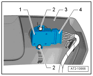
- Disconnect the connector -4-.
- Remove the bolts -2-.
- Remove -1- from the trim -3-.
Installing
Install in reverse order of removal. Note the following:
Installation notes, for example tightening specifications, replacing components. Refer to → Chapter "Overview - Seat Pan, Seat Adjustment Actuator/Switch".
Lumbar Support Adjustment Motors -V125-/-V126-/-V129-/-V130-, Removing and Installing
Special tools and workshop equipment required
- Pop Rivet Pliers -VAG1753B-
- Drill
- Protective eyewear
Removing
WARNING
- Follow all Safety Precautions when working with pyrotechnic components. Refer to → Chapter "Pyrotechnic Components Safety Precautions".
- Before handling pyrotechnic components (for example, disconnecting the connector), the person handling it must "discharge static electricity". This can be done by touching the door striker, for example.
- Remove the front seat. Refer to → Chapter "Front Seat, Removing and Installing".
- Fasten the front seat on the Engine/Transmission Holder - Seat Repair Fixture -VAS6136-. Refer to → Chapter "Front Seat, Mounting on Fixture for Seat Repair".
- Remove backrest cover with backrest cushion:
- For the standard seat/sport seat (manual or power). Refer to → Chapter "Backrest Cover and Padding, Removing and Installing, Standard/Sport Seat".
- For the super sport seat. Refer to → Chapter "Backrest Cover and Cushion, Removing and Installing, Super Sport Seat".
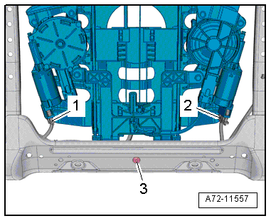
- Detach electrical harness connectors -1 and 2- at the lumbar support forward/back and height adjustment motors.
WARNING
Danger of eye injury.
Wear protective eyewear.
- Drill out rivet -3-.
- Free up the electric wiring harness on the lumbar support.
- Move the lower lumbar support -1- forward, disengage it from the backrest frame -2--arrows- and remove it.
Installing
- Attach the upper lumbar support -1- in the backrest frame -2--arrows- and move it down and to the rear.
- Make sure the metal washer -3- is inserted into the lumbar support -2- from the front before riveting -4-.
- Rivet lumbar support to the backrest frame.
Installation is performed in reverse order of removal, while noting the following:
WARNING
- Follow all Safety Precautions when working with pyrotechnic components. Refer to → Chapter "Pyrotechnic Components Safety Precautions".
- Before handling pyrotechnic components (for example, connecting the connector), the person handling it must "discharge static electricity". This can be done by touching the door striker, for example.
- Observe all measures when installing the front seat. Refer to → Chapter "Front Seat, Removing and Installing".
Installation notes, for example tightening specifications, replacing components. Refer to → Chapter "Overview - Front Backrest, Lumbar Support".