Audi A6 Typ 4G: General Information
Anti-Lock Braking System (ABS) Repair Information
ABS malfunctions do not affect the brake system and the booster. The conventional brake system remains operative even without ABS. A change in braking behavior should be checked. When the ABS indicator lamp comes on, the rear wheels can lock up early when braking.
 WARNING
- The ABS is always maintenance-free.
- Testing, assembly, and repair work may only be performed by qualified personnel.
- By not observing the points described in the repair manual, the system can be damaged and vehicle safety could be compromised.
Vehicles with high-voltage system
WARNING
Pay attention to the general warnings when working on a high-voltage system. Refer to → Electrical System Hybrid; Rep. Gr.93; High-Voltage System General Warnings.
All Vehicles
- Before servicing the ABS system, determine the cause of the damage using OBD.
- When installing a new hydraulic control module, the coding must be checked using the Vehicle Diagnostic Tester.
- Disconnect the battery ground cable when the ignition is switched off.
- When handling brake fluid, observe the relevant safety precautions and notes. Refer to → Chapter "General Information, Brake Fluid".
- Bleed the brake system with the Brake Charger/Bleeder Unit -VAS5234- for all work that requires opening the hydraulic system. High and low pressure testing should also be performed on the brake system. Refer to → Chapter "Leak Test".
- During the final road test, ensure that a ABS-controlled braking is performed at least once (pulsation must be felt at the brake pedal). Use the Vehicle Diagnostic Tester.
Component Location Overview
Overview - ABS/ESP
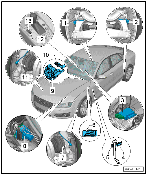
1 - Right Rear ABS Wheel Speed Sensor -G44-
- Checking using the Vehicle Diagnostic Tester in Guided Fault Finding
- Overview. Refer to → Chapter "Overview - Rear Axle Speed Sensor".
2 - Left Rear ABS Wheel Speed Sensor -G46-
- Checking using the Vehicle Diagnostic Tester in Guided Fault Finding
- Overview. Refer to → Chapter "Overview - Rear Axle Speed Sensor".
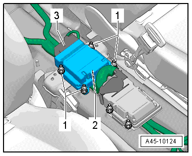
3 - Sensor Electronics Control Module -J849-
- Component location: under the center console extension
- Checking using the Vehicle Diagnostic Tester in Guided Fault Finding
- Removing and installing. Refer to → Chapter "Sensor Electronics Control Module, Removing and Installing".
4 - Brake Lamp Switch -F-
- Component location: on the brake pedal
- Removing and installing. Refer to → Chapter "Brake Lamp Switch, Removing and Installing".
5 - Brake Pedal
- Overview. Refer to → Chapter "Overview - Brake Pedal".
6 - Diagnostic Connection
- Component location. Refer to → Fig. "Diagnostic connection component location".
7 - Left Front ABS Wheel Speed Sensor -G47-
- Checking using the Vehicle Diagnostic Tester in Guided Fault Finding
- Overview. Refer to → Chapter "Overview - Front Axle Speed Sensor".
8 - ABS Hydraulic Unit -N55- with ABS Control Module -J104-
- The hydraulic unit and control module form the hydraulic control unit.
- Overview. Refer to → Chapter "Overview - Control Module and Hydraulic Unit".
9 - Steering Column Electronics Control Module -J527-
- With Airbag Spiral Spring/Return Spring with Slip Ring -F138- and Steering Angle Sensor -G85-
- Removing and installing. Refer to → Electrical Equipment; Rep. Gr.94; Steering Column Switch Module; Steering Column Electronics Control ModuleJ527, Removing and Installing.
10 - Return Ring
- Installed location: installed on the steering column with the slip ring
11 - Right Front ABS Wheel Speed Sensor -G45-
- Checking using the Vehicle Diagnostic Tester in Guided Fault Finding
- Overview. Refer to → Chapter "Overview - Front Axle Speed Sensor".
12 - -AUTO HOLD- Button -E540-
- Component location: in the center console
- Removing and installing. Refer to → Electrical Equipment; Rep. Gr.96; Controls; Electromechanical Parking Brake ButtonE538/-AUTO HOLD- ButtonE540, Removing and Installing.
13 - Electromechanical Parking Brake Button -E538-
- Component location: in the center console
- Removing and installing. Refer to → Electrical Equipment; Rep. Gr.96; Controls; Electromechanical Parking Brake ButtonE538/-AUTO HOLD- ButtonE540, Removing and Installing.
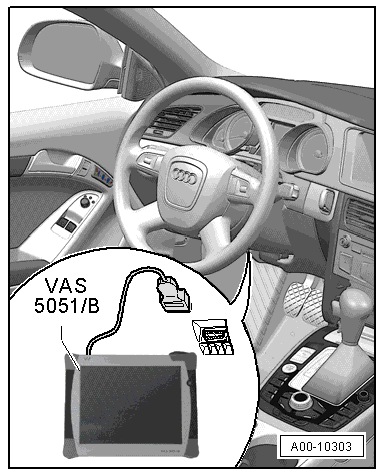
Diagnostic connection component location
- Component location: the diagnostic connection for the Vehicle Diagnostic Tester is located in the driver side footwell.
Sensor Electronics Control Module -J849- Tightening Specification
- Tighten the nuts -1- to 9 Nm
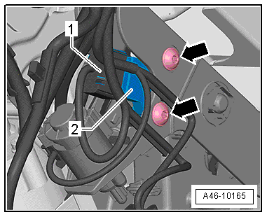
Brake Pedal Position Sensor -G100- - Tightening Specification
- Tighten the bolts -arrows- to 8 Nm.