Audi A6 Typ 4G: Selector Lever Handle, Removing and Installing
Special tools and workshop equipment required
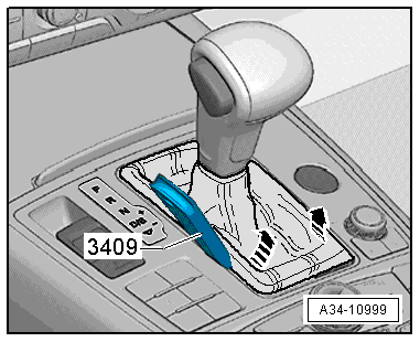
- Trim Removal Wedge -3409-
- The cable ties or the assembly aid for the button on the handle. The assembly aid is already installed at the factory when a new handle is ordered.
Removing
- Press the button on the electro-mechanical parking brake to activate it.
- Move the selector lever into "N".
 Note
Note
Both the selector lever handle and the selector lever boot are removed.
- Carefully pry out the selector lever boot on the side -arrows- with the Trim Removal Wedge -3409- or with a finger.
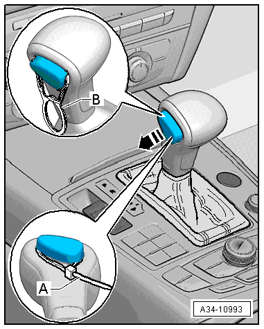
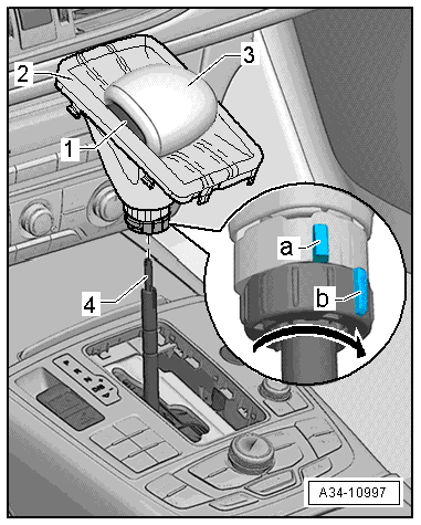
- Remove the locking button from the selector lever handle -arrow- and secure it with a cable tie -A- or an assembly aid -B-, as illustrated.
Note
The assembly aid -B- is already installed at the factory when a new handle is ordered. Remove the assembly aid only after the new handle is installed. This locking strap can be used again as an assist tool.
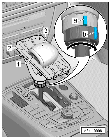
- Fold the selector lever boot -2- upward and over the selector lever handle -3-.
- Turn the locking ring all the way in direction of -arrow-. The markings -a- and -b- no longer line up.
- Remove the selector lever handle and selector lever boot without touching the locking button -1-.
Installing
- In order to install the selector lever handle, the locking button must be pulled out all the way and secured either with a cable tie -A- or with the assembly tool -B- supplied with a new handle.
If the locking button was not properly secured when the handle was being removed and it falls back inside the handle, then it must be pulled out again and secured:
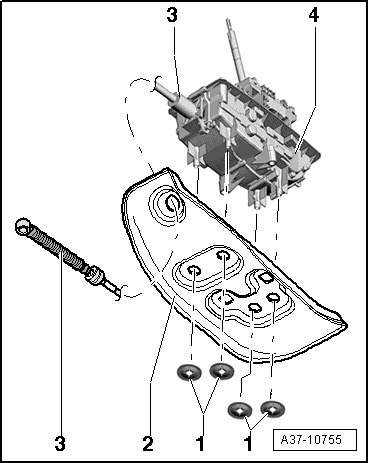
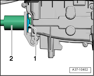
- Tape an adhesive pad or two-sided tape -2- to the locking button -1-.
Note
- As an alternative, use a 15 mm suction cup.
- Remove the adhesive pad or the two-sided tape after the handle has been installed. Make sure there is no adhesive left over.
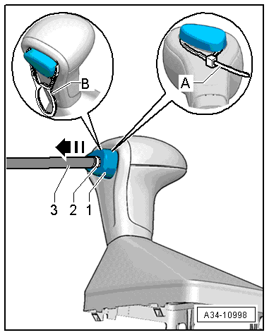
- Push on the adhesive surface using a tool -3- with a clean, flat surface as illustrated and pull out the locking button -arrow-.
- Secure the pulled-out locking button with a cable tie -A- or an assembly tool -B- as illustrated.
- Remove the adhesive pad or the two-sided tape -2- and clean the locking button -1-.
- Move the selector lever into "N".
Note
Pull on the rod -4- to move the selector lever.
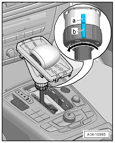
- Fold the selector lever boot -2- upward and over the selector lever handle -3-.
- Turn the locking ring all the way in direction of -arrow-. The markings -a- and -b- no longer line up.
- Press the selector lever handle with the locking button on the driver side completely onto the selector lever until it locks in.
- Turn the locking ring all the way in direction of -arrow- until it locks and the markings -a- and -b- line up.
 Caution
Danger of causing damage to the selector lever handle.
The locking ring can be turned only when the handle is installed completely.
- Remove cable ties or assembly tools. The locking button mechanism will engage in the vertical groove on the selector lever. If necessary, press the locking button into the selector lever handle.
- Move the button mechanism through "R" and "S" to perform the function test.
- If the selector lever positions cannot be reached, remove the handle again, refer to → Chapter "Selector Lever Handle, Removing and Installing".
- Pull the selector lever boot downward and attach it to the Multimedia System Control Head -E380-.
Selector Mechanism, Removing and Installing
Special tools and workshop equipment required
- Pry lever -80-200-
- Engine and Gearbox Jack -VAS6931-
- Engine/Gearbox Jack - Gearbox Support -T10337-
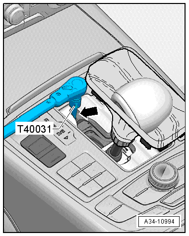
- Socket And Key -T40031-
Removing
- Remove the selector lever handle, refer to → Chapter "Selector Lever Handle, Removing and Installing".
- Move the selector lever into "D".
- Insert the Socket And Key -T40031- through the opening -arrow- in the selector mechanism and loosen the bolt on the selector lever cable approximately one turn.
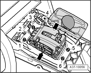
- Disconnect the connectors -2- and -4-.
Note
- The illustration does not show the insulation mat.
- A second technician is needed to remove the shift mechanism under the vehicle.
- Ignore -arrows-.
- Remove the insulation mat over the shift mechanism.
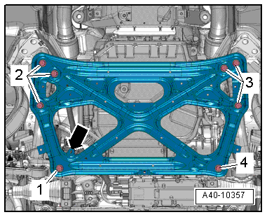
- Remove the bolts -1, 3, 5 and 6-.
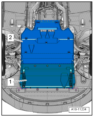
- Remove the noise insulations -1- and -2-, refer to → Body Exterior; Rep. Gr.66; Noise Insulation; Noise Insulation, Removing and Installing.
- Remove the subframe crossbrace, refer to → Suspension, Wheels, Steering; Rep. Gr.40; Subframe; Subframe Crossbrace, Removing and Installing.
Caution
The suspension components could be damaged.
Do not rest the vehicle on its wheels if the subframe mount, the steering gear or the subframe crossbrace are not installed correctly.
Vehicles with a 6-cylinder or 8-cylinder engine:
- Remove the left and right front muffler, refer to → Rep. Gr.26; Exhaust Pipes/Mufflers; Overview - Muffler.
Vehicles with a 6-cylinder TDI engine:
- Remove the front exhaust pipe, refer to → Rep. Gr.26; Exhaust Pipes/Mufflers; Overview - Muffler.
All vehicles:
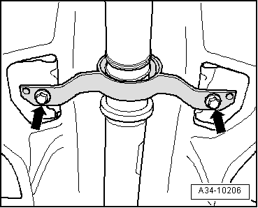
- Remove the bolts -arrows- for the driveshaft intermediate bearing.
- Lower the driveshaft.
- Remove the lock washers -1- (if equipped) from the noise insulation -2-.
- Pull the noise insulation off the function unit -4- for the selector lever cable -3- and push it forward.
- Remove the selector lever cable clip -1- sideways.
- Remove the selector lever cable -2- from the selector mechanism.
Note
Do not bend or kink the selector lever cable.
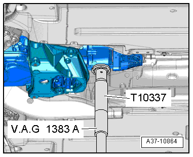
- Mount the Engine/Gearbox Jack - Gearbox Support -T10337- on the Engine and Gearbox Jack -VAS6931- and attach it under the transmission.
- Raise the transmission slightly.
 WARNING
There is the risk of an accident.
The Engine and Gearbox Jack -VAS6931- may only be used during assembly and must not sit unsupervised under the vehicle.
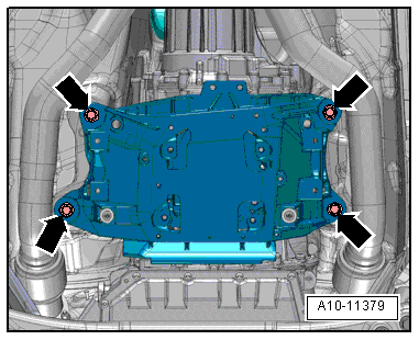
- Remove the bolts from the tunnel crossmember -arrows-.
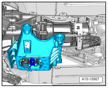
- Lower the transmission to dimension -a- using the Engine and Gearbox Jack -VAS6931-.
- Dimension -a- = maximum 70 mm.
- Remove the selector mechanism function unit.
Installing
Install in reverse order of removal. Note the following:
- Install the selector mechanism function unit and tighten it from the top.
- Install selector lever cable, refer to → Chapter "Selector Lever Cable, Removing and Installing".
- Adjust the selector lever cable, refer to → Chapter "Selector Lever Cable, Checking and Adjusting".
- Check the selector mechanism, refer to → Chapter "Gearshift Mechanism, Checking".
- Install the driveshaft intermediate bearing.
- Install the selector lever handle, refer to → Chapter "Selector Lever Handle, Removing and Installing".
- Perform "Guided Functions" using the Vehicle Diagnostic Tester after removing and installing the selector mechanism function unit, refer to → Chapter "Transmission Guided Functions".
Gearshift Mechanism, Checking
WARNING
There is a risk of injury and accident from accidentally engaging a gear when the engine is running.
- Shift the transmission into "P" and set the parking brake to lock the electro-mechanical parking brake before working on a running engine.
- Pay attention to the safety precautions when driving, refer to → Chapter "Road Test with Testing Equipment Safety Precautions".
- Perform all tests. If the specified values are not reached, adjust the selector lever cable (refer to → Chapter "Selector Lever Cable, Checking and Adjusting") and perform "Guided Fault Finding" using the Vehicle Diagnostic Tester.
Overview:
- 1. Selector mechanism function test.
- 2. Selector Lever Handle Locking Button, Checking.
1. Selector Mechanism Functionality Test
- Never operate the starter when the selector lever is in "R", "D/S" and the "tiptronic gate".
- If selector lever position "N" is selected at speeds greater than 5 km/h, the shift lock solenoid must not engage and block the selector lever. The selector lever can be moved into a another gear.
- For speeds below 2 km/h (almost standstill) and shifting into selector lever position "N", the shift lock solenoid must only engage after approximately 1 second. The selector lever can be moved out of "N" only when the brake pedal is pressed.
Selector lever in "P":
- Press the button on the electro-mechanical parking brake to activate it.
- Turn off the ignition.
- Selector lever is locked and cannot be shifted out of position "P" while locking button on selector lever handle is pressed.
- Turn on the ignition.
Note
Press the Access/Start Authorization Button -E408- briefly to get "ignition on".
- Do not press the brake pedal.
- Selector lever is locked and cannot be shifted out of position "P" while locking button on selector lever handle is pressed. The Shift Lock Solenoid -N110- locks the selector lever.
- Press the brake pedal and hold it down.
- The Shift Lock Solenoid -N110- unlocks the selector lever. It is possible to shift into a gear. Press the button in the selector lever handle and slowly move the selector lever from "P" and through "R, N, D, S". While doing this, make sure the Transmission Range Display -Y6- inside the instrument cluster matches the actual position of the selector lever.
- Pull the selector lever toward the rear out of "D/S" and then release it again.
- The selector lever moves automatically back into "D/S". The Transmission Range Display -Y6- must change from "D" to "S1" in the instrument cluster and then go back to "D" after pulling the lever toward the rear.
The selector lever is in "N" and the ignition is turned on:
- Do not press the brake pedal.
- After a short waiting period: The selector lever is locked and cannot be moved out of "N" position despite pressing locking button on selector lever handle. The Shift Lock Solenoid -N110- locks the selector lever.
- Press the brake pedal.
- The Shift Lock Solenoid -N110- unlocks the selector lever. It is possible to shift into "D/S".
The selector lever is in "D/S" and the ignition is on:
- Move the selector lever into the "tiptronic gate".
- The "D/S" in the Selector Lever Transmission Range Position Display Unit -Y26- must turn off and the "+" and "-" must turn on.
- The Transmission Range Display -Y6- inside the instrument cluster must change from "D" to "M1" when the selector lever moves into the "tiptronic gate"
- Do not move the selector lever into "P" but rather, for example, into "N".
- Turn off the ignition.
- A warning message must appear in the instrument cluster.
- The vehicle cannot be locked.
- Move the selector lever into "P".
- Turn off the ignition.
- The vehicle can be locked.
If the specified values are not obtained:
- Perform Guided Fault Finding using the Vehicle Diagnostic Tester.
- Adjust the selector lever cable, refer to → Chapter "Selector Lever Cable, Checking and Adjusting".
- Locking button on selector lever handle, checking.
2. Selector Lever Handle Locking Button, Checking
Make sure locking button moves easily.
- It must be possible to press the locking button without using great force.
- After releasing, the locking button must come all the way back out by itself.
If the specified values are not obtained:
- Make sure the selector lever handle is installed correctly, refer to → Chapter "Selector Lever Handle, Removing and Installing".
- Make sure the selector lever is not bent.
Function test:
- The ignition is switched on.
The locking button on the selector lever handle must be pressed for the following shifts. If it is not pressed, the selector lever cannot be shifted into the specified position.
- Move the selector lever from "P" into "R" and press the brake pedal at the same time.
- "N" into "R"; stationary, press the brake pedal after waiting longer
- "R" into "P"
If the specified values are not obtained:
- Make sure the selector lever handle is installed correctly, refer to → Chapter "Selector Lever Handle, Removing and Installing".
- Check the connectors on the selector mechanism.
- Perform Guided Fault Finding using the Vehicle Diagnostic Tester and check the Shift Lock Solenoid -N110-.
- Adjust the selector lever cable, refer to → Chapter "Selector Lever Cable, Checking and Adjusting".
