Audi A6 Typ 4G: Multifunction Steering Wheel
Multifunction Steering Wheel, General Information
Buttons are integrated in the steering wheel for easier operation of Infotainment, telephone and the navigation system. On vehicles with Tiptronic, rocker switches are also installed on the left and right.
The Multifunction Steering Wheel Control Module -J453- (in the right button) reads out the button information and transfers them over the LIN bus to the Steering Column Electronics Control Module -J527-. From the Steering Column Electronics Control Module -J527-, the information is transferred to the individual components via the CAN Bus (comfort) and the Data Bus On Board Diagnostic Interface -J533-.
Fault finding is performed via "Guided Fault Finding" using Vehicle Diagnostic Tester.
Overview - Multifunction Steering Wheel
Overview - Multifunction Steering Wheel, 4-Spoke Steering Wheel
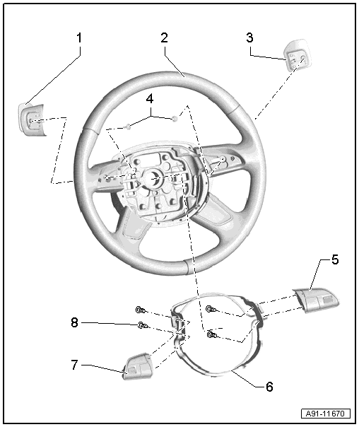
1 - Tiptronic Downshift Button on Steering Wheel -E439-
- Removing and installing. Refer to → Chapter "Tiptronic Downshift/Upshift Button on Steering Wheel -E439-/-E438-, Removing and Installing".
2 - 4-Spoke Steering Wheel
3 - Tiptronic Upshift Button on Steering Wheel -E438-
- Removing and installing. Refer to → Chapter "Tiptronic Downshift/Upshift Button on Steering Wheel -E439-/-E438-, Removing and Installing".
4 - Bolt
- 1 Nm
5 - Right Multifunction Buttons On Steering Wheel -E441-
- Removing and installing. Refer to → Chapter "Multifunction Steering Wheel Buttons, 4-Spoke Steering Wheel, Removing and Installing".
6 - Trim Molding
7 - Left Multifunction Buttons On Steering Wheel -E440-
- Removing and installing. Refer to → Chapter "Multifunction Steering Wheel Buttons, 4-Spoke Steering Wheel, Removing and Installing".
8 - Bolt
- 1 Nm
Overview - Multifunction Steering Wheel, 3-Spoke Steering Wheel Overview - Multifunction Steering Wheel, 3-Spoke Steering Wheel
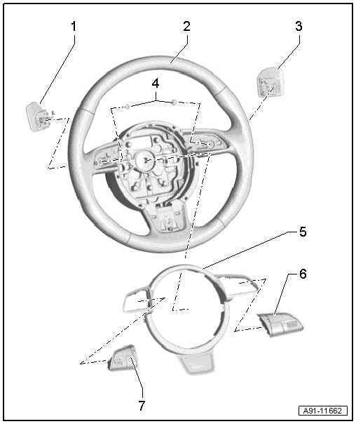
1 - Tiptronic Downshift Button on Steering Wheel -E439-
- Removing and installing. Refer to → Chapter "Tiptronic Downshift/Upshift Button on Steering Wheel -E439-/-E438-, Removing and Installing".
2 - 3-Spoke-Steering Wheel
3 - Tiptronic Upshift Button on Steering Wheel -E438-
- Removing and installing. Refer to → Chapter "Tiptronic Downshift/Upshift Button on Steering Wheel -E439-/-E438-, Removing and Installing".
4 - Bolt
- 1 Nm
5 - Trim Molding
6 - Right Multifunction Buttons On Steering Wheel -E441-
- Removing and installing. Refer to → Chapter "Multifunction Buttons, Removing and Installing, 3-Spoke Steering Wheel".
7 - Left Multifunction Buttons On Steering Wheel -E440-
- Removing and installing. Refer to → Chapter "Multifunction Buttons, Removing and Installing, 3-Spoke Steering Wheel".
Right/Left Multifunction Buttons on Steering Wheel -E441-/-E440-, Removing and Installing
Multifunction Steering Wheel Buttons, 4-Spoke Steering Wheel, Removing and Installing
Special tools and workshop equipment required
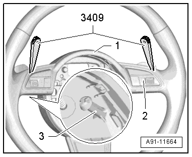
- Trim Removal Wedge -3409-
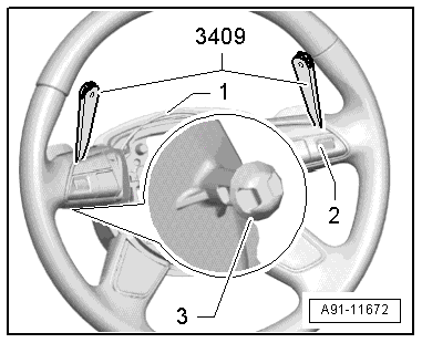
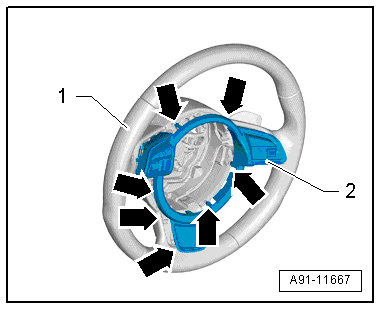
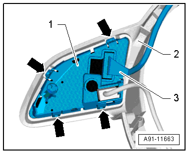
The multifunction buttons -2- are attached to the trim -1-. The trim -1- and the multifunction buttons -2- are attached to the steering wheel. The multifunction buttons -2- have an extra retainer -3-.
While removing, first make sure the trim -1- can be loosened by hand (approximately 5 mm). Then, using the Trim Removal Wedge -3409-, open the retainers -3- on the multifunction buttons -2- and remove the trim -1- together with the multifunction buttons -2-.
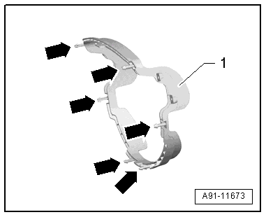
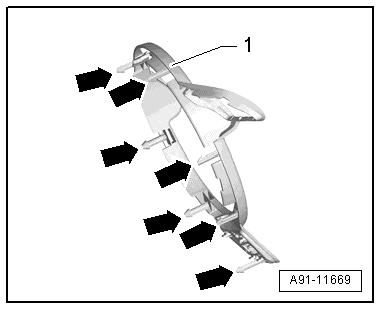
Trim retainers
1 - Trim Molding
Arrows - tabs
Multifunction button retainers
1 - Multifunction button
2 - Catch
- Turn off the ignition and all electrical consumers and remove the ignition key.
Removing
- Remove the driver airbag. Refer to → Body Interior; Rep. Gr.69; Driver Side Airbag; Airbag Unit with Igniter, Removing and Installing.
- Remove the connecting wires from the guides in the steering wheel.
- Loosen the trim panel -2- with the multifunction buttons by hand -arrows- and remove it approximately 5 mm from the steering wheel -1-.
- Release the multifunction buttons -2- with the Trim Removal Wedge -3409- next to the retainers -3-. Use the Trim Removal Wedge -3409- as shown in the illustration.
- While doing this, be careful of the connectors to the tiptronic switches -2-.
- Unlock and disconnect the connector -2- from the multifunction buttons.
- Remove the trim panel with multifunction buttons from the steering wheel.
The multifunction buttons are attached to the trim.
- Unlock and disconnect the connector from the multifunction button.
- Remove the bolts -3- and push the multifunction button -2- out of the trim panel -1-.
The additional wire on the right multifunction button remains on the button.
Installing
- Install in reverse order of removal. Note the following:
- Place the trim panel with mounted multifunction buttons onto the steering wheel.
- Route the connection cable for the tiptronic switch -2- as illustrated.
- Route the rest of the connector cables, including plugs, into the guides in the steering wheel.
- Push the trim panel -2- with multifunction buttons onto the steering wheel -1- until it engages.
- Finally, check the steering wheel to make sure the wiring is correct.
Multifunction Buttons, Removing and Installing, 3-Spoke Steering Wheel
Special tools and workshop equipment required
- Trim Removal Wedge -3409-
The multifunction buttons -2- are clipped in the trim molding -1-. The trim -1- and the multifunction buttons -2- are attached to the steering wheel. The multifunction buttons -2- have an extra retainer -3-.
While removing, first make sure the trim -1- can be loosened by hand (approximately 5 mm). Then, using the Trim Removal Wedge -3409-, open the retainers -3- on the multifunction buttons -2- and remove the trim -1- together with the multifunction buttons -2-.
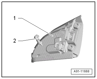
Trim retainers
1 - Trim Molding
Arrows - tabs
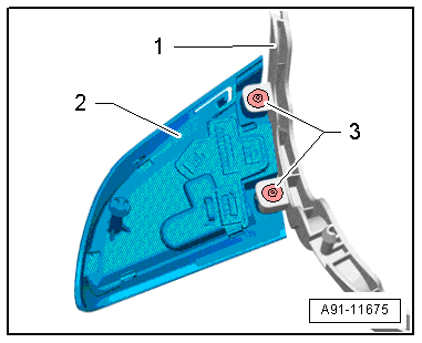
Multifunction button retainers
1 - Multifunction button
2 - Catch
- Turn off the ignition and all electrical consumers and remove the ignition key.
Removing
- Remove the driver airbag. Refer to → Body Interior; Rep. Gr.69; Driver Side Airbag; Airbag Unit with Igniter, Removing and Installing.
- Remove the connecting wires from the guides in the steering wheel.
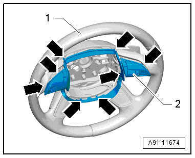
- Loosen the trim panel -2- with the multifunction buttons by hand -arrows- and remove it approximately 5 mm from the steering wheel -1-.
- Release the multifunction buttons -2- with the Trim Removal Wedge -3409- next to the retainers -3-. Use the Trim Removal Wedge -3409- as shown in the illustration.
- While doing this, be careful of the connectors to the tiptronic switches -2-.
- Unlock and disconnect the connector -2- from the multifunction buttons.
- Remove the trim panel with multifunction buttons from the steering wheel.
The multifunction buttons are attached to the trim.
- Disconnect and remove the connector -3- from the multifunction button -1-.
- Open the clips -arrows- and push the multifunction button -1- out of the trim -2-.
The additional wire on the right multifunction button remains on the button.
Installing
- Install in reverse order of removal. Note the following:
- Place the trim panel with mounted multifunction buttons onto the steering wheel.
- Route the connection cable for the tiptronic switch -2- as illustrated.
- Route the rest of the connection cable, including the connector, into the guides inside the steering wheel.
- Push the trim panel -2- with multifunction buttons onto the steering wheel -1- until it engages.
- Finally, check the steering wheel to make sure the wiring is correct.
Tiptronic Downshift/Upshift Button on Steering Wheel -E439-/-E438-, Removing and Installing
- Turn off the ignition and all electrical consumers and remove the ignition key.
Removing
- Remove the trim molding with the multifunction buttons. Refer to → Chapter "Multifunction Buttons, Removing and Installing, 3-Spoke Steering Wheel" for the 4-spoke steering wheel; refer to → Chapter "Multifunction Steering Wheel Buttons, 4-Spoke Steering Wheel, Removing and Installing" for the 3-spoke steering wheel.
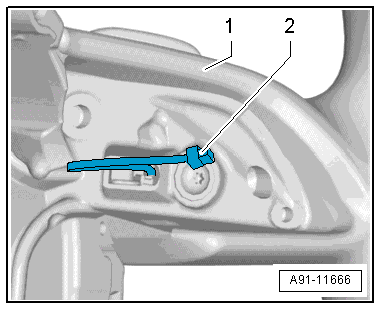
- Remove the bolt -2- on the steering wheel -1- and remove the tiptronic switch -3- with connector cable to the rear.
Installing
- Install in reverse order of removal.
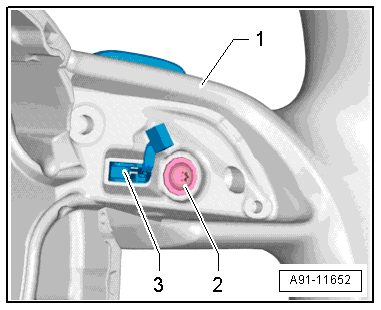
- Pay attention to the location of the connecting cable -2- to the multifunction button.
