Audi A6 Typ 4G (2011–2018) Workshop Manual / Electrical System / Communication / Rear Seat Entertainment System (RSE)
Audi A6 Typ 4G: Rear Seat Entertainment System (RSE)
Rear Seat Entertainment, General Information
The "Rear Seat Entertainment system" 9WP consists of:
- Information Electronics Control Module 2 -J829-, DVD Player -R7-/SD card reader between the rear seats in the rear panel
- Displays on the front seat back rests (Multimedia Display Unit 1 -Y22- left rear /Multimedia Display Unit 2 -Y23- right rear)
- Multimedia Control Head 2 -E499- in the rear center console
- Headphones connection inside the rear center console
- External Audio Source Connection 2 -R321- (interface) inside the rear center console
Repairing fiber-optic cables. Refer to → Electrical Equipment General Information; Rep. Gr.97; Wiring Harness and Connector Repairs; Fiber-Optic Cables, Repairing.
Overview - Rear Seat Entertainment System
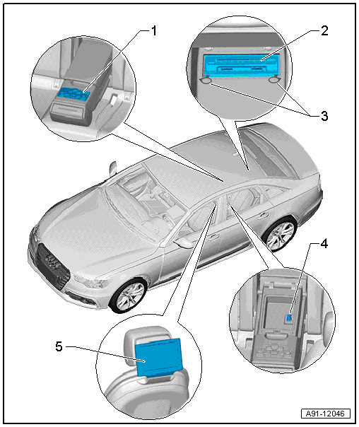
1 - Multimedia Control Head 2 -E499-
- Connector assignment. Refer to → Chapter "Multimedia Control Head 2 -E499- Connector Assignment".
- Connector assignment, radio. Refer to → Chapter "Multimedia Control Head 2 -E499- Connector Assignment, Radio".
- Removing and installing. Refer to → Chapter "Multimedia Control Head 2 -E499-, Removing and Installing".
2 - Information Electronics Control Module 2 -J829-
- Connector assignment. Refer to → Chapter "Information Electronics Control Module 2 -J829- Connector Assignment".
- Removing and installing. Refer to → Chapter "Information Electronics Control Module 2 -J829-, Removing and Installing".
3 - Radio Removal Tool -T10057-
4 - External Audio Source Connection 2 -R231-
- Connector assignment. Refer to → Chapter "External Audio Source Connection 2 -R231- Connector Assignment".
- Removing and installing. Refer to → Chapter "External Audio Source Connection 2 -R321-, Removing and Installing".
5 - Multimedia Display Unit 1 -Y22-/Multimedia Display Unit 2 -Y23-
- 4 Nm
- Connector assignment. Refer to → Chapter "Multimedia Display Unit 1/2 -Y22-/-Y23-, Connector Assignment".
- Removing and installing. Refer to → Chapter "Multimedia Display Unit 1/2 -Y22-/-Y23-, Removing and Installing".
- Display Bolts
- Quantity: 2
