Audi A6 Typ 4G: Overview - Center Console Controls
Overview - Center Console Controls
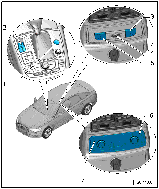
1 - Access/Start Authorization Button -E408-
- Removing and installing. Refer to → Chapter "Access/Start Authorization Button -E408-, Removing and Installing".
2 - Electromechanical Parking Brake Button -E538-
- Depending on the vehicle equipment level with -Auto Hold- Button -E540-
- Removing and installing. Refer to → Chapter "Electromechanical Parking Brake Button -E538-/ -AUTO HOLD- Button -E540-, Removing and Installing".
3 - Right Rear Heated Seat Regulating Switch -E129-
- Removing and installing. Refer to → Chapter "Left and Right Rear Heated Seat Regulating Switch -E128-/-E129- Removing and Installing, with Base A/C System".
4 - Rear Temperature Selection Potentiometer -G538-
- Country-specific and equipment level
- Common part with trim, cannot be replaced separately
- Replacing. Refer to → Body Interior; Rep. Gr.68; Center Console; Overview - Center Console.
5 - Left Rear Heated Seat Regulating Switch -E128-
- Removing and installing. Refer to → Chapter "Left and Right Rear Heated Seat Regulating Switch -E128-/-E129- Removing and Installing, with Base A/C System".
6 - Right Rear Heated Seat Regulating Switch -E129-
- Equipment level
- Integrated in Rear A/C Display Control Head -E265-. Cannot be replaced separately if faulty.
- Replacing the Rear A/C Display Control Head -E265-. Refer to → Heating, Ventilation, and Air Conditioning; Rep. Gr.87; Display and Control Head; Display and Control Head, Removing and Installing
7 - Left Rear Heated Seat Regulating Switch -E128-
- Equipment level
- Integrated in Rear A/C Display Control Head -E265-. Cannot be replaced separately if faulty.
- Replacing the Rear A/C Display Control Head -E265-. Refer to → Heating, Ventilation, and Air Conditioning; Rep. Gr.87; Display and Control Head; Display and Control Head, Removing and Installing
Overview - Controls in the Center Console, Version 1, Market-Specific
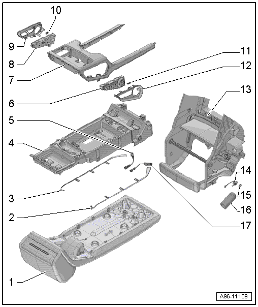
1 - Center Armrest Cushion
2 - Left Fiber Optic Cable
- For ambient lighting
3 - Right Fiber Optic Cable
- for ambient lighting
4 - Armrest-Lower Section
5 - Right Rear Center Console Ambient Lighting Bulb 2 -L198-
6 - Left Rear Seat Massage Button -E409-
- Removing and installing. Refer to → Chapter "Left/Right Rear Seat Massage Button -E409-/-E410-, Removing and Installing".
7 - Trim
- For the center armrest
8 - Right Rear Seat Massage Button -E410-
- Removing and installing. Refer to → Chapter "Left/Right Rear Seat Massage Button -E409-/-E410-, Removing and Installing".
9 - Right Trim
- For the rear seat massage button
10 - Clamp
- Quantity: 3
11 - Clamp
- Quantity: 3
12 - Left Trim
- For the rear seat massage button
13 - Center Armrest
14 - Rear Center Console Ambient Lighting Contact Switch -F501-
- Removing and installing. Refer to → Chapter "Rear Center Console Ambient Lighting Contact Switch -F501-, Removing and Installing".
15 - Clamp
- Quantity: 2
16 - Grommet
17 - Left Rear Center Console Ambient Lighting Bulb 1 -L197-
Overview - Controls in the Center Console, Version 2, Market-Specific
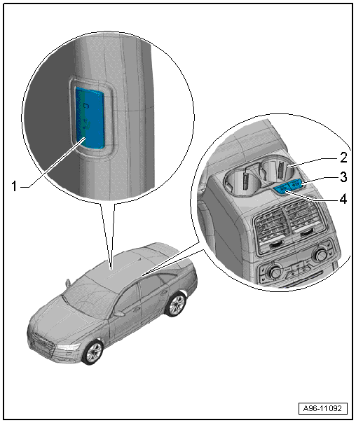
1 - Air Ionization System Button -E677-
- Country
- Only in the "Comfort" mode
- Removing and installing. Refer to → Chapter "Air Ionization System Button -E677-, Removing and Installing".
2 - Cupholder with Heating and Cooling Element -Z105-
- Removing and installing: Refer to → Body Interior; Rep. Gr.68; Center Console; Overview - Center Console
3 - Cupholder Cooling Element Button -E674-
- Removing and installing. Refer to → Chapter "Cupholder Cooling Element Button -E674-/Cupholder Heating Element Button -E675-, Removing and Installing".
4 - Cupholder Heating Element Button -E675-
- Removing and installing. Refer to → Chapter "Cupholder Cooling Element Button -E674-/Cupholder Heating Element Button -E675-, Removing and Installing".
Overview - Luggage Compartment Controls
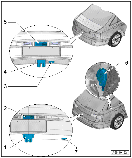
1 - Rear Lid Contact Switch - Avant
- Removing and installing. Refer to → Chapter "Rear Lid Contact Switch, Removing and Installing".
2 - Rear Lid Lock Cylinder Unlock Button -F248- - Avant
- Removing and installing. Refer to → Chapter "Rear Lid Lock Cylinder Unlock Button -F248-, Removing and Installing, Avant".
3 - Rear Lid Lock Button in Luggage Compartment -E406- - Sedan
- Versions with Locking Mechanism Button in the Rear Lid -E806-.
- Removing and installing. Refer to → Chapter "Rear Lid Lock Button in Luggage Compartment -E406-, Removing and Installing, Avant".
4 - Rear Lid Contact Switch - Sedan
- Removing and installing. Refer to → Chapter "Rear Lid Contact Switch, Removing and Installing".
5 - Rear Lid Lock Cylinder Unlock Button -F248- - Sedan
- Removing and installing. Refer to → Chapter "Rear Lid Lock Cylinder Unlock Button -F248-, Removing and Installing, Sedan".
6 - Rear Lid Warning Buzzer -H32-
- The buzzer is activated by closing the rear lid using the rear lid remote release button in the front door
- Removing and installing. Refer to → Chapter "Rear Lid Warning Buzzer -H32-, Removing and Installing".
7 - Rear Lid Lock Button in Luggage Compartment -E406- - Avant
- Versions with Locking Mechanism Button in the Rear Lid -E806-.
- Removing and installing. Refer to → Chapter "Rear Lid Lock Button in Luggage Compartment -E406-, Removing and Installing, Sedan".
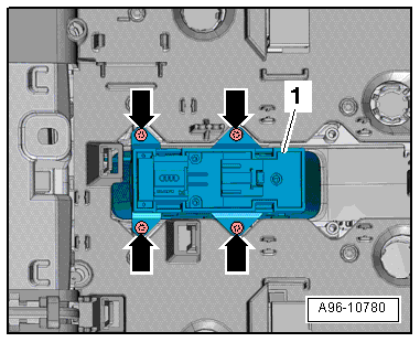
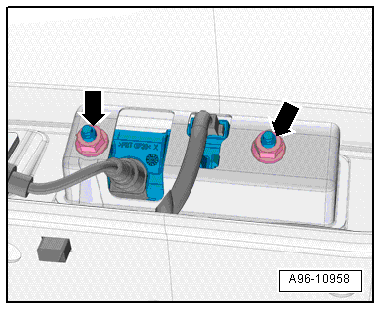
Tightening Specification: Anti-Theft Protection to Rear Lid Lock Cylinder Unlock Button -F248-.
- Tighten the nuts -arrows- to 6 Nm.
Overview - Roof Trim Panel Controls
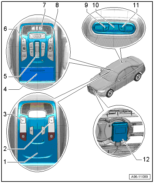
1 - Front Interior Lamp/Reading Lamp
- Vehicles without an eyeglass compartment
- Removing and installing. Refer to → Chapter "Front Interior Lamp/Reading Lamp, Removing and Installing, without Eyeglass Compartment".
2 - Front Passenger Reading Lamp Button -E458-
- "Basis"
- Common part with interior lamp/front reading lamp
3 - Driver Reading Lamp Button -E457-
- "Basis"
- Common part with interior lamp/front reading lamp
4 - Front Interior Lamp/Reading Lamp
- Vehicles with an eyeglass compartment
- Removing and installing. Refer to → Chapter "Front Interior Lamp/Reading Lamp, Removing and Installing, with Eyeglass Compartment".
5 - Sunroof Button -E325-
- Removing and installing. Refer to → Chapter "Sunroof Button -E325-, Removing and Installing".
6 - Left Front Reading Lamp Button -E633-
- "Comfort"
- Removing and installing. Refer to → Chapter "Left/Right Front Reading Lamp Button -E633-/-E634-, Removing and Installing".
7 - Garage Door Opener Control Head -E284-
- Removing and installing. Refer to → Chapter "Garage Door Opener Control Head -E284-, Removing and Installing".
8 - Right Front Reading Lamp Button -E634-
- "Comfort"
- Removing and installing. Refer to → Chapter "Left/Right Front Reading Lamp Button -E633-/-E634-, Removing and Installing".
9 - Left Rear Reading Lamp Switch -E454-
10 - Rear Interior Lamp
- Removing and installing. Refer to → Chapter "Rear Interior/Reading Lamp, Removing and Installing".
11 - Right Rear Reading Lamp Switch 1 -E455-
12 - Garage Door Opener Control Module -J530-
- Overview. Refer to → Chapter "Overview - Control Modules".
Tightening Specification for the Front Interior Lamp/Reading Lamp
- Tighten the screw -3- to 2 Nm.
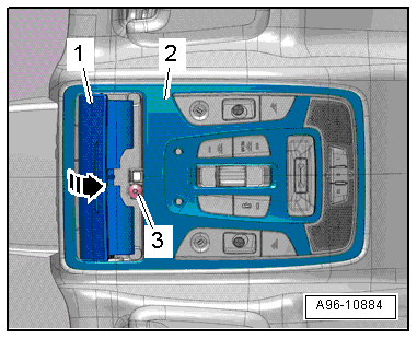
Tightening Specification Sunroof Button -E325-
- Tighten the screws -arrows- to 0.65 Nm.