Audi A6 Typ 4G: Overview - Front Brakes
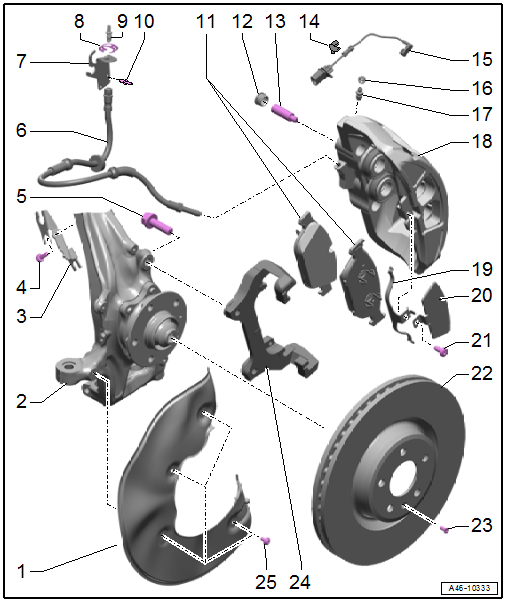
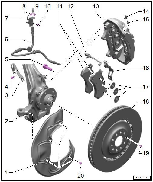
Overview - Front Brakes, Steel Brakes, 1LA/1LJ
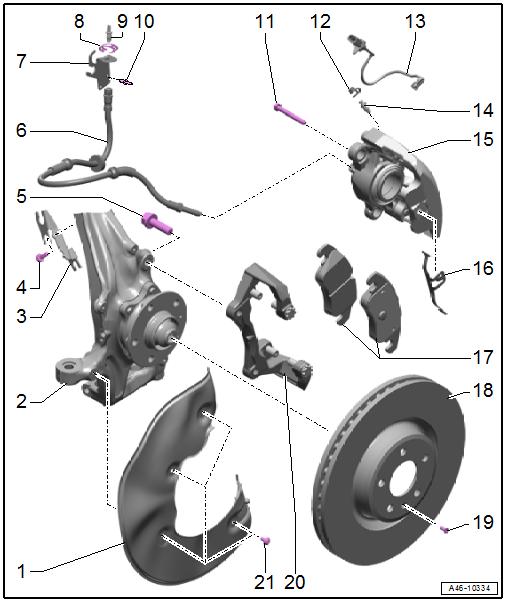
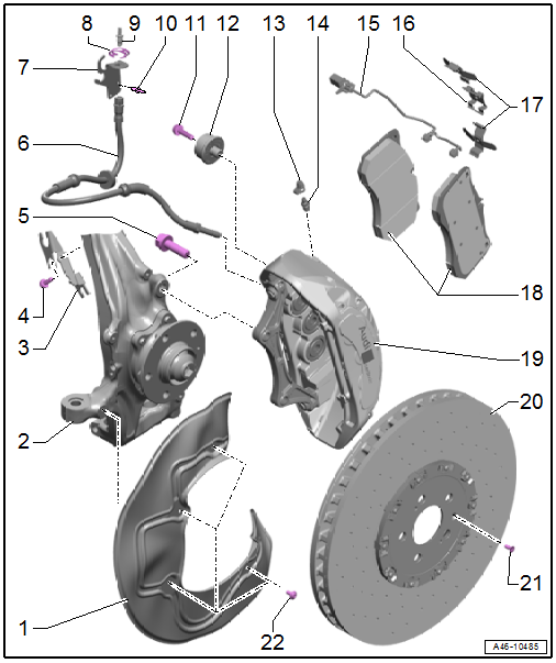
1 - Brake Shield
2 - Stub Axle Carrier
3 - Bracket
- For brake hose and wire
4 - Bolt
- 9 Nm
5 - Bolt
- 196 Nm
- With a washer
- Quantity: 2
- Replace after removing
6 - Brake Hose
- Pay attention to the correct routing: make sure the brake hose is not blocked, bent or rubbing against the vehicle
- Replace if damaged
- Make sure that tabs are properly seated in the grooves on the bracket.
- Tightening specification, brake hose to brake caliper, 20 Nm
7 - Bracket
- For brake hose
8 - Spring
- Replace if damaged
9 - Brake Line
- Tightening specification, brake line to brake hose, 16 Nm
10 - Rivet
- Quantity: 2
11 - Bolt
- 30 Nm
- Quantity: 2
12 - Protective Dust Cap
13 - Brake Pad Wear Sensor
- Left Front Brake Pad Wear Sensor -G34-, Right Front Brake Pad Wear Sensor -G35-
- For inner brake pad
- Replace if damaged
- Refer to → Chapter "Brake Pad Wear Indicator Wire, Removing and Installing, Steel Brakes, 1LA/1LJ"
14 - Bleed Screw
- 13 Nm
- Refer to → Chapter "Hydraulic System, Standard Bleeding"
15 - Brake Caliper
- Allocation. Refer to the Parts Catalog.
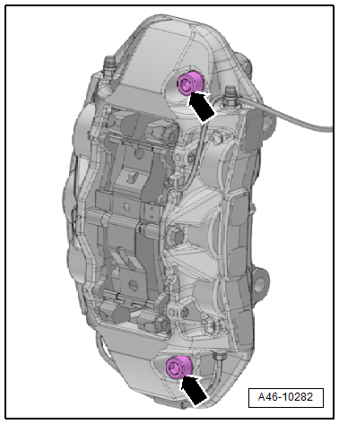
- Do not loosen the brake caliper threaded connections. Refer to → Fig. "Do not loosen the brake caliper threaded connections.".
- Servicing. Refer to → Chapter "Brake Caliper Piston, Removing and Installing, 1LA/1LJ".
 Note
Note
- Depending on the model there are two balance weights installed in each front brake caliper.
16 - Balance Spring
- Make sure the balance spring is correctly installed
- Tab of the balance spring engages into the brake caliper
17 - Brake Pads
- Allocation. Refer to the Parts Catalog.
- Inner brake pad with brake pad wear sensor
- Checking pad thickness. Refer to → for the wear limit.
- Always replace on both sides of the axle
18 - Brake Rotor
- Allocation. Refer to the Parts Catalog.
- Wear limit. Refer to → Chapter "Technical Data, Brakes"
- Always replace on both sides of the axle
- Do not use force to separate the brake rotor from the wheel hub. If required use rust remover otherwise there will be damage to the brake rotors
19 - Bolt
- 10 Nm
20 - Brake Carrier
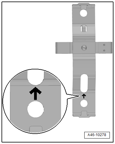
- Do not loosen the retaining pin. Refer to → Fig. "Do not loosen the retaining pin on the brake carrier".
- Brake Caliper with Brake Carrier, removing and installing. Refer to → Chapter "Brake Caliper, Removing and Installing, Steel Brakes, 1LA/1LJ".
21 - Bolt
- 10 Nm
- Quantity: 4
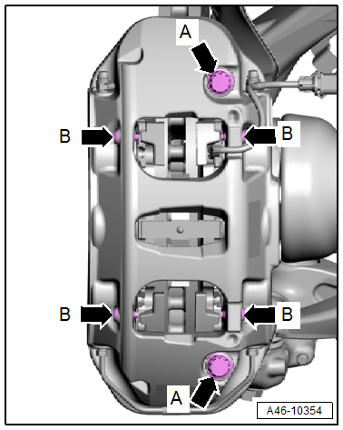
Do not loosen the brake caliper threaded connections.
 Caution
Risk of malfunction.
Do not loosen the bolts -arrows- on the brake caliper.
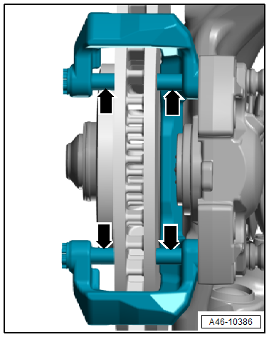
Do not loosen the retaining pin on the brake carrier
Caution
Risk of malfunction.
Do not loosen the retaining pins -arrows- on the brake carrier.
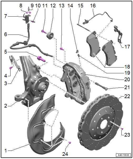
Overview - Front Brakes, Steel Brakes, 1LF/1LL/1ZK/FM0
1 - Brake Shield
2 - Stub Axle Carrier
3 - Bracket
- For brake hose and wire
4 - Bolt
- 9 Nm
5 - Bolt
- 196 Nm
- With a washer
- Quantity: 2
- Replace after removing
6 - Brake Hose
- 20 Nm (brake hose to brake caliper)
- Pay attention to the correct routing: make sure the brake hose is not blocked, bent or rubbing against the vehicle
- Replace if damaged
- Make sure that tabs are properly seated in the grooves on the bracket.
7 - Bracket
- For brake hose
8 - Spring
- Replace if damaged
9 - Brake Line
- 16 Nm (brake line to brake hose)
10 - Rivet
- Quantity: 2
11 - Brake Pads
- Allocation. Refer to the Parts Catalog.
- Inner brake pad with brake pad wear sensor
- Checking pad thickness. Refer to → for the wear limit.
- Always replace on both sides of the axle
12 - Protective Cap
13 - Guide Pin
- 55 Nm
- Seal with a protective cap
14 - Clip
15 - Brake Pad Wear Sensor
- Left Front Brake Pad Wear Sensor -G34-/Right Front Brake Pad Wear Sensor -G35-
- For inner brake pad
- Replace if damaged
- Refer to → Chapter "Brake Pad Wear Indicator Wire, Removing and Installing, Steel Brakes, 1LF/1LL"
16 - Protective Dust Cap
17 - Bleed Screw
- 13 Nm
- Refer to → Chapter "Hydraulic System, Standard Bleeding"
18 - Brake Caliper
- Allocation. Refer to the Parts Catalog.
- Servicing. Refer to → Chapter "Brake Caliper Piston, Removing and Installing, 1LF/1LL".
Note
- Depending on the model there are two balance weights installed in each front brake caliper.
19 - Balance Spring
- Make sure the cover and balance spring are installed correctly
- Tab of the balance spring engages into the brake caliper
- Tip of the balance spring fits under the trim
20 - Trim
- Make sure the cover and balance spring are installed correctly
- Tip of the balance spring fit into the brake caliper
- Tip of the balance spring fits under the trim
21 - Bolt
- 22 Nm
22 - Brake Rotor
- Allocation. Refer to the Parts Catalog.
- Wear limit. Refer to → Chapter "Technical Data, Brakes"
- Always replace on both sides of the axle
- Do not use force to separate the brake rotor from the wheel hub. If required use rust remover otherwise there will be damage to the brake rotors
23 - Bolt
- 10 Nm
24 - Brake Carrier
- Bolt to wheel bearing housing
- Brake Caliper with Brake Carrier, removing and installing. Refer to → Chapter "Brake Caliper, Removing and Installing, Steel Brakes, 1LF/1LL".
25 - Bolt
- 10 Nm
- Quantity: 4
Overview - Front Brakes, 1LP
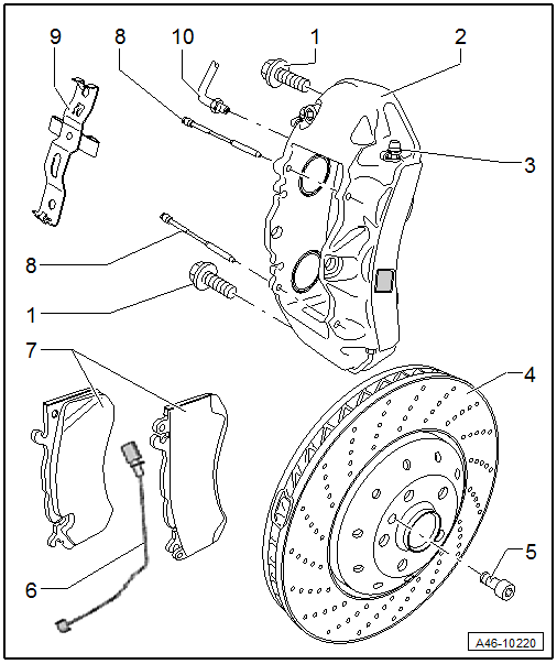
1 - Bolt
- 196 Nm
Note
Loosen only the coil spring bolts
2 - Brake Caliper
- Do not loosen any screws on the brake caliper.
Note
- Depending on the model there are two balance weights installed in each front brake caliper.
3 - Bleed Screw
4 - Brake Rotor
- Allocation. Refer to the Parts Catalog.
- Always replace on both sides of the axle
- Wear limit
- Clean and lubricate contact surfaces between brake rotor and wheel hub. Refer to the Parts Catalog.
5 - Bolt
- 10 Nm
- Brake rotor to wheel hub
6 - Brake Pad Wear Wire
- on inner brake pad
7 - Brake Pads
- With the brake pad wear wire on the inside of the brake pad
- Check the pad thickness.
- Wear limit.
- Before installing the brake pads, clean the pad guide surface and coat it with a film of grease. Grease. Refer to Parts Catalog.
- Make sure it is in the installation position
8 - Brake Pad Pins
- Make sure it is in the installation position
- Press all the way from the inside toward the outside
9 - Brake Pad Spring
- Make sure it is in the installation position
10 - Brake Line Hose
- 19 Nm
Note
Do not loosen when changing brake pads
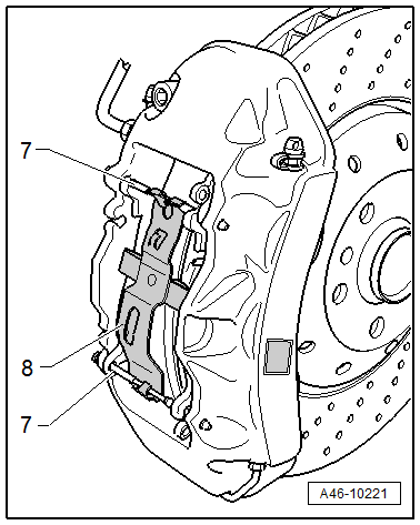
Installed position for the brake pad spring brake pad pin -7-, brake pad pin -8-
Overview - Brake Caliper Balance Weight
Depending on the model there are two balance weights installed in each front brake caliper.
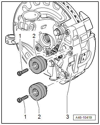
1 - Bolt
- 10 Nm
- Replace after removing
2 - Vibration Damper
- Installed twice in each front brake caliper
3 - Brake Caliper
Overview - Front Brakes, Steel Brakes, 1LU
1 - Brake Shield
2 - Stub Axle Carrier
3 - Bracket
- For brake hose and wire
4 - Bolt
- 9 Nm
5 - Bolt
- 196 Nm
- With a washer
- Quantity: 2
- Replace after removing
6 - Brake Hose
- 20 Nm (brake hose to brake caliper)
- Pay attention to the correct routing: make sure the brake hose is not blocked, bent or rubbing against the vehicle
- Replace if damaged
- Make sure that tabs are properly seated in the grooves on the bracket.
7 - Bracket
- For brake hose
8 - Spring
- Replace if damaged
9 - Brake Line
- 16 Nm (brake line to brake hose)
10 - Rivet
- Quantity: 2
11 - Brake Pads
- Allocation. Refer to the Parts Catalog.
- Inner brake pad with brake pad wear sensor
- Checking pad thickness. Refer to → for the wear limit.
- Always replace on both sides of the axle
12 - Brake Pad Wear Sensor
- Left Front Brake Pad Wear Sensor -G34-/Right Front Brake Pad Wear Sensor -G35-
- For inner brake pad
- Replace if damaged
- Removing and installing. Refer to → Chapter "Brake Pad Wear Indicator Wire, Removing and Installing, Steel Brakes, 1LU".
13 - Brake Caliper
- Allocation. Refer to the Parts Catalog.
- Do not loosen the brake caliper threaded connections. Refer to → Fig. "Do not loosen the brake caliper threaded connections.".
- Servicing. Refer to → Chapter "Brake Caliper Piston, Removing and Installing, 1LU/1LM/1LX/1LN/1LW".
Note
- Depending on the model there are two balance weights installed in each front brake caliper.
14 - Protective Dust Cap
15 - Bleed Screw
- 13 Nm
16 - Brake Pad Spring
- Note the installation position. Refer to → Fig. "Installation position of the brake pad spring".
- Replace when pads are replaced.
- Make sure then fits correctly inside the brake caliper
17 - Shim
- With adhesive pad
- Quantity: 6
- Insert into the brake caliper pistons before inserting the outer brake pads
Note
- Use new shims when installing new brake pads. Insert the shims into the brake pistons before inserting the brake pads.
- If the old brake pads are reinstalled, insert the brake pads with the shims attached into the brake caliper.
18 - Brake Rotor
- Allocation. Refer to the Parts Catalog.
- Wear limit. Refer to → Chapter "Technical Data, Brakes"
- Always replace on both sides of the axle
- Do not use force to separate the brake rotor from the wheel hub. If required use rust remover otherwise there will be damage to the brake rotors
19 - Bolt
- 10 Nm
20 - Bolt
- 10 Nm
- Quantity: 4
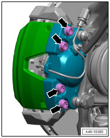
Do not loosen the brake caliper threaded connections.
Caution
Risk of malfunction.
- Do not loosen the bolts -arrows- on the brake caliper.
- Do not remove the guide pins -arrows B-.
Note
The guide pins -B arrows- are only replaced on the ceramic brakes.
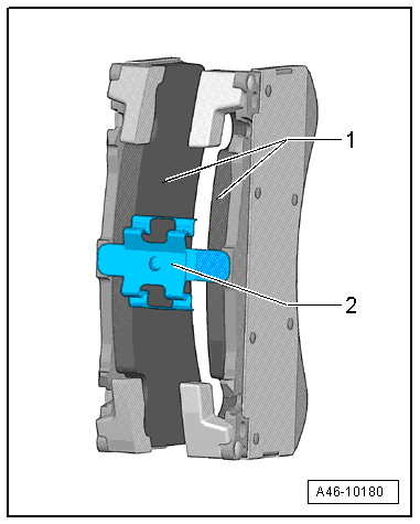
Installation position of the brake pad spring
Note
Pay attention to the correct installation position of the brake pad spring -2- between the brake pads -1-.
Overview - Front Brakes, Steel Brakes, 1LM/1LX
1 - Brake Shield
2 - Stub Axle Carrier
3 - Bracket
- For brake hose and wire
4 - Bolt
- 9 Nm
5 - Bolt
- 196 Nm
- With a washer
- Quantity: 2
- Replace after removing
6 - Brake Hose
- 20 Nm (brake hose to brake caliper)
- Make sure the brake hose is routed correctly. Make sure the brake hose is not blocked, bent or rubbing against the vehicle.
- Replace if damaged
- Make sure that tabs are properly seated in the grooves on the bracket.
7 - Bracket
- For brake hose
8 - Spring
- Replace if damaged
9 - Brake Line
- 14 Nm (Brake line to brake hose)
10 - Rivet
- Quantity: 2
11 - Bolt
- 9 Nm
- Quantity: 4
12 - Balance Weight
- Quantity: 2
13 - Bolt
- 30 Nm
- For the tension strut
- Replace after removing
14 - Protective Cap
15 - Brake Pad Pin
- Quantity: 2
- Replace when pads are replaced.
- Note the installation position
- Drive out from the outside toward the inside
16 - Brake Pad Wear Sensor
- Left Front Brake Pad Wear Sensor -G34-/Right Front Brake Pad Wear Sensor -G35-
- For inner brake pad
- Replace if damaged
- Cannot be removed without being damaged
- Removing and installing. Refer to → Chapter "Brake Pad Wear Indicator Wire, Removing and Installing, Steel Brakes, 1LM/1LX".
17 - Brake Pad Spring
- Note the installation position. Refer to → Fig. "Installed Position for the Brake Pad Spring".
- Replace when pads are replaced.
- Make sure then fits correctly inside the brake caliper
18 - Brake Pads
- Checking pad thickness. Refer to → for the wear limit.
- Always replace on both sides of the axle
- Allocation. Refer to the Parts Catalog.
- Note installed position: inner brake pad with brake pad wear sensor mount
19 - Bleed Screw
- 13 Nm
20 - Brake Caliper
- May not be removed from the brake carrier. Refer to → Fig. "Do not loosen the caliper/brake carrier bolted connections."
- Allocation. Refer to the Parts Catalog.
- Servicing. Refer to → Chapter "Brake Caliper Piston, Removing and Installing, 1LU/1LM/1LX/1LN/1LW".
Note
- Depending on the model there are two balance weights installed in each front brake caliper.
21 - Tension Strut
- Replace when pads are replaced.
22 - Brake Rotor
- Wear limit. Refer to → Chapter "Technical Data, Brakes".
- Allocation. Refer to the Parts Catalog.
- Always replace on both sides of the axle
23 - Bolt
- 10 Nm
24 - Bolt
- 10 Nm
- Quantity: 4
Do not loosen the caliper/brake carrier bolted connections.
Caution
Risk of malfunction.
Do not loosen the bolts -arrows- on the brake caliper.
Installed Position for the Brake Pad Spring
- The "arrow" points in the direction of forward wheel rotation.
Overview - Front Brakes, Ceramic, 1LN/1LW
1 - Brake Shield
2 - Stub Axle Carrier
3 - Bracket
- For brake hose and wire
4 - Bolt
- 9 Nm
5 - Bolt
- 196 Nm
- With a washer
- Quantity: 2
- Replace after removing
6 - Brake Hose
- Make sure the brake hose is routed correctly. Make sure the brake hose is not blocked, bent or rubbing against the vehicle.
- Replace if damaged
- Make sure that tabs are properly seated in the grooves on the bracket.
- 20 Nm (brake hose to brake caliper)
7 - Bracket
- For brake hose
8 - Spring
- Replace if damaged
9 - Brake Line
- 14 Nm (brake line to brake hose)
10 - Rivet
- Quantity: 2
11 - Bolt
- 9 Nm
- Quantity: 4
12 - Balance Weight
- Quantity: 2
13 - Protective Cap
14 - Bleed Screw
- 13 Nm
15 - Brake Pad Wear Sensor
- Left Front Brake Pad Wear Sensor -G34-/Right Front Brake Pad Wear Sensor -G35-
- Replace if damaged
- Cannot be removed without being damaged
- Removing and installing. Refer to → Chapter "Brake Pad Wear Indicator Wire, Removing and Installing, Ceramic Brakes, 1LN/1LW".
16 - Bracket
- For brake pad wear sensor electrical wire
- Replace if damaged
- Make sure then fits correctly inside the brake caliper
17 - Brake Pad Springs
- Note the installation position
- Replace when pads are replaced.
- Make sure then fits correctly inside the brake caliper
18 - Brake Pads
- Checking pad thickness. Refer to → for the wear limit.
- Always replace on both sides of the axle
- Allocation. Refer to the Parts Catalog.
- Note the installation position
19 - Brake Caliper
- 24 Nm (guide pin for the brake pads). Refer to → Fig. "The threaded connections -arrow A- on the brake caliper must not be loosened.".
- May not be removed from the brake carrier. Refer to → Fig. "The threaded connections -arrow A- on the brake caliper must not be loosened."
- Allocation. Refer to the Parts Catalog.
- Servicing. Refer to → Chapter "Brake Caliper Piston, Removing and Installing, 1LU/1LM/1LX/1LN/1LW".
Note
- Depending on the model there are two balance weights installed in each front brake caliper.
- Refer to → Chapter "Overview - Brake Caliper Balance Weight"
20 - Brake Rotor
- Allocation. Refer to the Parts Catalog.
- Brake Rotor Thickness. Refer to → Chapter "Ceramic Brake Rotor, Determining Wear".
- Additionally check for:
- Cracks in connection area. Refer to → Chapter "Cracks in Ceramic Brake Rotor Connection Area".
- Chamfer. Refer to → Chapter "Chamfer".
- Nicks. Refer to → Chapter "Nicks on Ceramic Brake Rotor".
- Crack in cooling channel. Refer to → Chapter "Crack in Cooling Channel".
- Always replace on both sides of the axle
- Make note of the direction of travel
21 - Bolt
- 10 Nm
22 - Bolt
- 10 Nm
- Quantity: 4
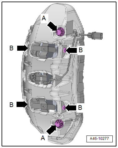
The threaded connections -arrow A- on the brake caliper must not be loosened.
Caution
Risk of malfunction.
- Do not loosen the bolts -arrows- on the brake caliper.
- Replace the guide pins -B arrows- after removing.
Tighten the guide pin -B- to 24 Nm.