Audi A6 Typ 4G: Selector Lever Cable, Removing and Installing
Special tools and workshop equipment required
- Pry lever -80-200-
- Trim Removal Wedge -3409-
- Engine and Gearbox Jack -VAS6931-
- Engine/Gearbox Jack - Gearbox Support -T10337-
- Socket And Key -T40031-
Removing
- Press the button on the electro-mechanical parking brake to activate it.
- Move the selector lever into "D".
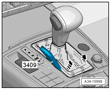
- Carefully pry out the selector lever boot on the side -arrows- using the Trim Removal Wedge -3409- or a finger and then fold it upward.
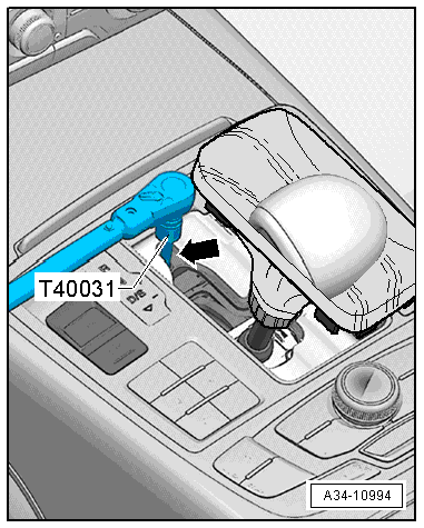
- Insert the Socket And Key -T40031- through the opening -arrow- in the selector mechanism and loosen the bolt on the selector lever cable approximately one turn.
 Note
Note
- Only loosen the clamping screw - do not remove it.
- The clamping screw is only accessible when the selector lever is in "D".
- The selector lever must remain in "D" when the clamping screw is loose.
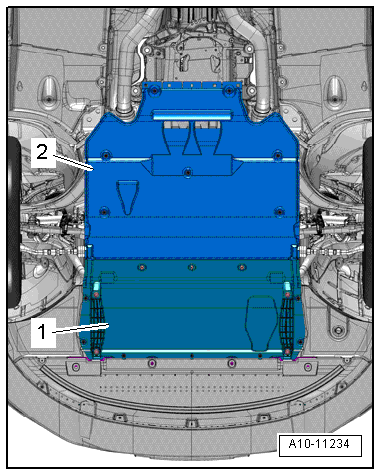
- Remove the noise insulations -1- and -2-, refer to → Body Exterior; Rep. Gr.66; Noise Insulation; Noise Insulation, Removing and Installing.
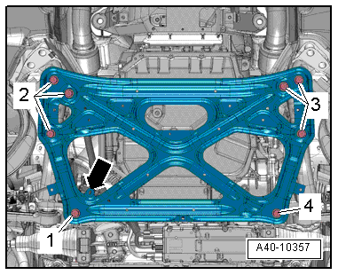
- Remove the subframe crossbrace, refer to → Suspension, Wheels, Steering; Rep. Gr.40; Subframe; Subframe Crossbrace, Removing and Installing.
 Caution
The suspension components could be damaged.
Do not rest the vehicle on its wheels if the subframe mount, the steering gear or the subframe crossbrace are not installed correctly.
Vehicles with a 6-cylinder or 8-cylinder engine:
- Remove the left and right front muffler, refer to → Rep. Gr.26; Exhaust Pipes/Mufflers; Overview - Muffler.
Vehicles with a 6-cylinder TDI engine:
- Remove the front exhaust pipe, refer to → Rep. Gr.26; Exhaust Pipes/Mufflers; Overview - Muffler.
All vehicles:
- Remove the lock washers -1- (if equipped) from the noise insulation -2-.
- Pull the noise insulation off the function unit -4- for the selector lever cable -3- and push it forward.
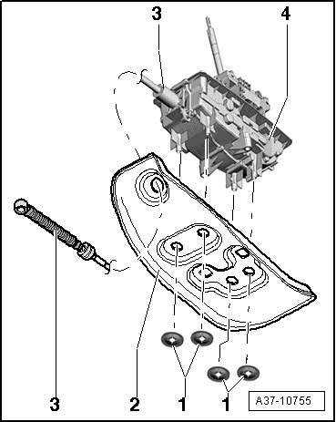
- Remove the selector lever cable clip -1- sideways.
- Remove the selector lever cable -2- from the selector mechanism.
Note
Do not bend or kink the selector lever cable.
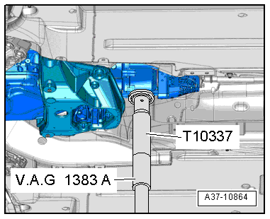
- Mount the Engine/Gearbox Jack - Gearbox Support -T10337- on the Engine and Gearbox Jack -VAS6931- and attach it under the transmission.
- Raise the transmission slightly.
 WARNING
There is the risk of an accident.
The Engine and Gearbox Jack -VAS6931- may only be used during assembly and must not sit unsupervised under the vehicle.
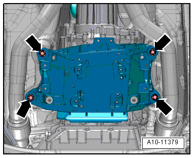
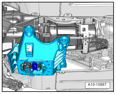
- Remove the bolts from the tunnel crossmember -arrows-.
- Lower the transmission to dimension -a- using the Engine and Gearbox Jack -VAS6931-.
- Dimension -a- = maximum 70 mm.
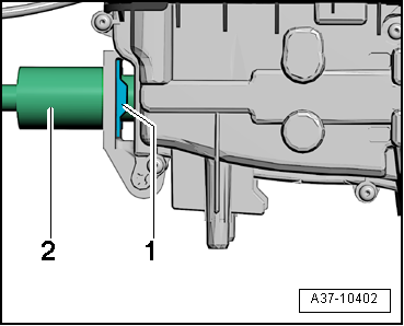
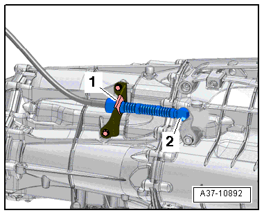
- Remove the selector lever cable ball socket -2- using the Pry Lever - 80-200- from the gearshift lever.
- Remove the clip -1- and remove the selector lever cable from the transmission.
- Depending on the version the lock nut can be installed instead of a clip -1-.
Installing
Install in reverse order of removal. Note the following:
Note
- Replace the lock washers for the noise insulation.
- Lubricate the cable eye and the ball socket on the selector lever cable with Polycarbamide Grease -G 052 142 A2- before installing.
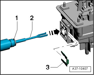
- Insert the o-ring -1- on the selector lever cable.
- Install the selector lever cable -2- into the gearshift mechanism function unit-arrow-.
- Secure the selector lever cable -2- with the clip-3-.
- Installed position: The angled end of the clip -1- faces the shift mechanism.
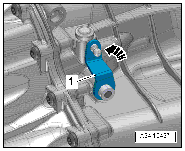
- Push the selector lever -1- on the transmission all the way to the back -arrow- until the parking lock locks into place.
- When parking lock is engaged, it must not be possible to turn the front wheels.
- Press the selector shaft lever forward three detents so the transmission is in "D".
- Make sure the selector lever inside the vehicle is also in "D".
- Carefully press the selector lever cable ball socket -2- in this position onto the selector shaft lever.
Note
Do not bend selector shaft lever when pressing on, otherwise shift mechanism can no longer be adjusted exactly.
- Secure the selector lever cable with the clip -1-.
- Depending on the version a lock nut can be installed instead of a clip -1-, tightening specification 13 Nm.
Note
Do not bend or kink the selector lever cable.
- Check the selector mechanism, refer to → Chapter "Gearshift Mechanism, Checking".
- Adjust the selector lever cable, refer to → Chapter "Selector Lever Cable, Checking and Adjusting".
Selector Lever Cable, Checking and Adjusting
Selector Lever Cable, Checking and Adjusting
Special tools and workshop equipment required
- Trim Removal Wedge -3409-
- Socket And Key -T40031-
Procedure
- Press the button on the electro-mechanical parking brake to activate it.
- Move the selector lever into "D".
- Carefully pry out the selector lever boot on the side -arrows- using the Trim Removal Wedge -3409- or a finger and then fold it upward.
- Insert the Socket And Key -T40031- through the opening -arrow- in the selector mechanism and loosen the bolt on the selector lever cable approximately one turn.
Note
- Only loosen the clamping screw - do not remove it.
- The clamping screw is only accessible when the selector lever is in "D".
- The selector lever must remain in "D" when the clamping screw is loose.
- Carefully move the selector forward and back gently without shifting into another selector lever position. This releases the tension in the selector lever cable.
- Tighten the clamping screw in this position with the Socket And Key -T40031- without touching the selector lever.
- Check the selector mechanism, refer to → Chapter "Gearshift Mechanism, Checking".
- Perform "Guided Functions" using the Vehicle Diagnostic Tester after adjusting the selector lever cable, refer to → Chapter "Transmission Guided Functions".
If shift mechanism does not function properly after adjusting selector lever cable:
- Bring the selector lever cable into the basic setting, refer to → Chapter "Selector Lever Cable, Bringing into Basic Setting".
Selector Lever Cable, Bringing into Basic Setting
Special tools and workshop equipment required
- Vehicle Diagnostic Tester
- Pry lever -80-200-
- Socket And Key -T40031-
Procedure
- Guided Fault Finding with the Vehicle Diagnostic Tester is completed; all faults have been corrected.
- Select the following menu items in Functions/Component selection"Guided Fault Finding" on theVehicle Diagnostic Tester:
- Drivetrain
- 0B5 - Transmission
- 01-OBD-capable systems
- 02-transmission electronics
- 02-Transmission electronics, functions
- 02-Measured values
- Select driving mode from the list.
- Compare the following displays:
- Measured value driving mode on the Vehicle Diagnostic Tester
- Selector lever position
- Selector Lever Transmission Range Position Display Unit -Y26- on the shift mechanism
- Transmission Range Display -Y6- in the instrument cluster
Conditions:
- The displays must match
If the displays do not match:
- Adjust the selector lever cable, refer to → Chapter "Selector Lever Cable, Checking and Adjusting".
If the individual displays cannot be reached by adjusting the selector lever cable:
Selector lever cable, bringing into basic setting:
- Remove the selector lever cable ball socket -2- using the Pry Lever - 80-200- from the gearshift lever.
Note
- Do not bend or kink the selector lever cable.
- Ignore item -1-.
- Push the selector lever -1- on the transmission all the way to the back -arrow- until the parking lock locks into place.
- When parking lock is engaged, it must not be possible to turn the front wheels.
- Press the selector shaft lever forward three detents so the transmission is in "D".
- Make sure the selector lever inside the vehicle is also in "D".
- Insert the Socket And Key -T40031- through the opening -arrow- in the selector mechanism and loosen the bolt on the selector lever cable approximately one turn.
Note
- Only loosen the clamping screw - do not remove it.
- The clamping screw is only accessible when the selector lever is in "D".
- The selector lever must remain in "D" when the clamping screw is loose.
- Remove the Socket And Key -T40031- from the torque wrench and let the move it through the opening -arrow- in the selector mechanism.
- Carefully press the selector lever cable ball socket -2- in this position onto the selector shaft lever.
Note
- Do not bend selector shaft lever when pressing on, otherwise shift mechanism can no longer be adjusted exactly.
- Ignore -item 1-.
- Select 02-measured values in Guided Fault Finding 02 transmission electronics on the Vehicle Diagnostic Tester
- Select driving mode from the list.
- Compare the following displays:
- Measured value driving mode on the Vehicle Diagnostic Tester
- Selector lever position
- Selector Lever Transmission Range Position Display Unit -Y26- on the shift mechanism
- Transmission Range Display -Y6- in the instrument cluster
Conditions:
- The displays must match
- Carefully move the selector forward and back gently without shifting into another selector lever position. This releases the tension in the selector lever cable.
- Tighten the clamping screw in this position with the Socket And Key -T40031- without touching the selector lever.
- Check the selector mechanism, refer to → Chapter "Gearshift Mechanism, Checking".
