Audi A6 Typ 4G: Steering Column, Checking for Damage
Visual Check
- Check whether steering column parts show signs of damage.
Functional Check
- Check whether steering column can be turned without catching or difficulty of movement.
- Check whether steering column can be easily adjusted laterally and vertically.
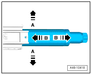
- Check if the tube clearly moves in direction of -arrow A- or direction of -arrow B-.
- If this is the case, the steering column must be replaced.
Steering Column, Handling and Transporting
Steering Column, Handling and Transporting, Manual
 WARNING
- The correct handling of the steering column must always be observed.
- Incorrect handling of steering column may cause damage to steering column and therefore lead to a safety risk.
Correct Handling and Transport of Steering Column
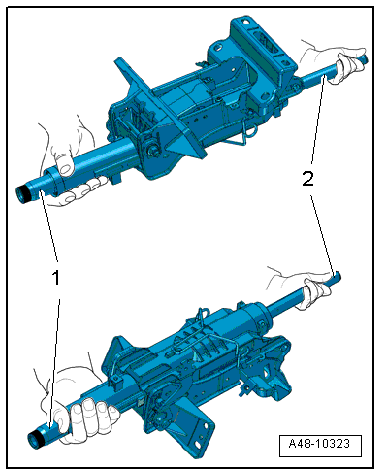
- Wearing gloves, hold the steering column with both hands and remove it from the shipping container.
- Hold the steering column by the upper column tube -1- and near the upper universal joint -2- as illustrated.
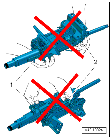
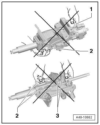
Incorrect Handling of Steering Column
Transporting at the following components leads to pre-damage to steering column:
1 - Release handle
2 - Weight balancing springs
- A steering column that has fallen onto a hard surface or shows signs of damage must not be installed in the vehicle.
- Do not lay the steering column on the splines.
- The splines must not get compressed.
Steering Column, Handling and Transporting, Power
WARNING
- The correct handling of the steering column must always be observed.
- Incorrect handling of steering column may cause damage to steering column and therefore lead to a safety risk.
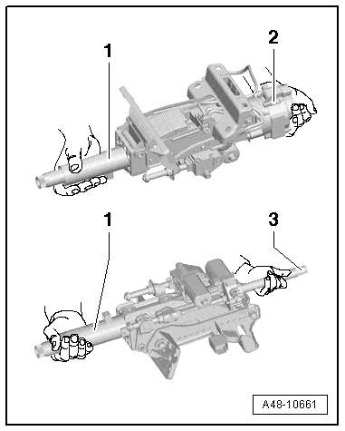
Correct Handling and Transport of Steering Column
- Wearing gloves, hold the steering column with both hands and remove it from the shipping container.
- Hold the steering column at the top of the steering rod tube -1-, or depending on the version near the dynamic steering adjuster -2-, or at the bottom of the steering rod tube -3- as illustrated.
Incorrect Handling of Steering Column
Transporting at the following components leads to pre-damage to steering column:
1 - Connector and wiring harness
2 - Spindles for the electric steering column adjustment
3 - Motors for the electric steering column adjustment
- A steering column that has fallen onto a hard surface or shows signs of damage must not be installed in the vehicle.
- Do not lay the steering column on the splines.
- The splines must not get compressed.
Steering Column, Removing and Installing
Special tools and workshop equipment required
- Torque Wrench 1331 5-50Nm -VAG1331-
Removing
WARNING
Note the following before removing the steering column:
Create a sketch showing the:
- Routing of the electrical wiring harnesses,
- Securing the electrical wiring harnesses,
- Cable tie locations.
This especially applies to the wiring harness to the Electronic Steering Column Lock Control Module -J764-.
Note the following before installing the steering column:
- Route the electrical wiring harnesses exactly the way they were before removal.
- Secure the electrical wiring harnesses exactly the way they were before removal.
- Install all the cable ties that were loosened or cut in the same locations when installing the steering column.
- Make sure the wiring harness to the Electronic Steering Column Lock Control Module -J764- is not pinched and does not come into contact with sharp edges when adjusting the steering column.
 Note
Note
- The steering column is delivered only as a complete replacement part. Service is not possible.
- Only the Electronic Steering Column Lock Control Module -J764- can be replaced separately.
- Straighten the wheels.
- Position the steering wheel as far down as possible using the full range of the steering column adjuster.
- Remove the steering wheel. Refer to → Chapter "Steering Wheel, Removing and Installing".
- Remove the driver side instrument panel cover. Refer to → Body Interior; Rep. Gr.68; Storage Compartments and Covers; Driver Side Instrument Panel Cover, Removing and Installing.
- If equipped, remove the driver side knee airbag with the bracket. Refer to → Body Interior; Rep. Gr.69; Knee Airbags; Knee Airbag with Igniter, Removing and Installing.
- Remove the footwell vent on the driver side. Refer to → Heating, Ventilation and Air Conditioning; Rep. Gr.87; Air Guide; Driver Side Footwell Vent, Removing and Installing.
- Remove the steering column trim. Refer to → Body Interior; Rep. Gr.68; Storage Compartments and Covers; Overview - Steering Column Trim Panel.
- Remove the steering column switch module. Refer to → Electrical Equipment; Rep. Gr.94; Steering Column Switch Module; Steering Column Switch Module, Removing and Installing.
WARNING
On dynamic steering system steering columns, never loosen or remove the dynamic steering unit bolts.
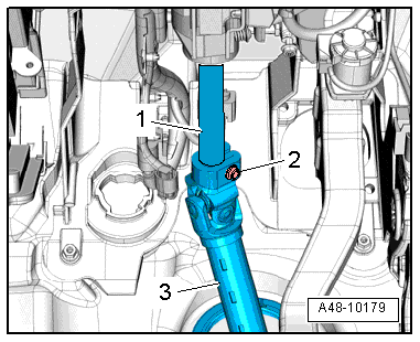
- Remove the bolt -2- and remove the steering intermediate shaft -3- from the steering column -1-.
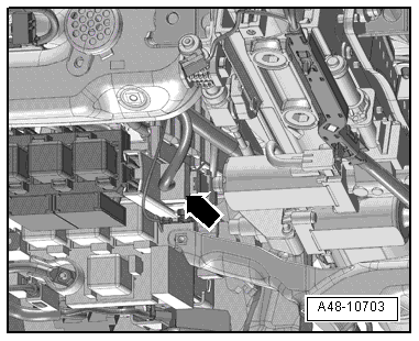
Applies to Power Steering Column
- Disconnect the connector -arrow- and free it up.
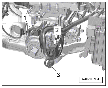
- Disconnect and free up the connectors -1, 2 and 3- for the dynamic steering (if equipped).
Applies to All
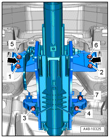
- Remove the steering column bolts -1 through 7- on the central tube while supporting the steering column from below with the hand.
- Pull the steering column back slightly, disengage it from the positioning holes -arrows- on the central tube and lower it.
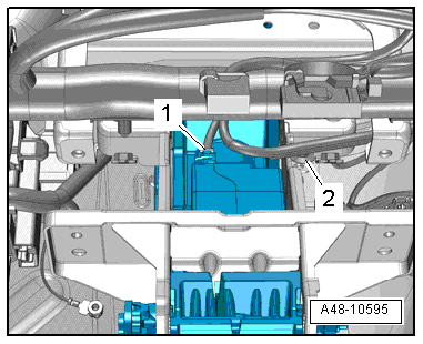
- Disconnect the connector -1- from the Electronic Steering Column Lock Control Module -J764- for vehicles with the lock lock-up system, free up the wiring harness -2- and remove the steering column.
Installing
Install in reverse order of removal. Note the following:
- If the steering column on a vehicle with the steering locking system was replaced, use the bolt installed in the new steering column for the Electronic Steering Column Lock Control Module -J764-.
Note
- If the steering column was replaced, use the bolt installed in the new steering column for the Electronic Steering Column Lock Control Module -J764-.
- Clean the threaded hole (for example, using a thread tap) before installing the new bolt -2-.
Applies to Vehicles with the Steering Lock Lock-Up System
- After connecting the connector, -1- make sure the wiring harness is secured by the clip -2-.
- If the steering column needs to be adjusted, be careful not to pinch the wiring harness -3- for the Electronic Steering Column Lock Control Module -J764--1- and make sure it does not come in contact with any sharp edges.
Follow the Assembly Sequence when Installing
- Position the steering column with the positioning pins -arrows- in the positioning holes on the central tube.
- Install all bolts loosely.
- First tighten the bolt -1- to the tightening specification.
- Then tighten the bolt -2- to the tightening specification.
- Then tighten the bolt -3 and 4- to the tightening specification.
- Then tighten the bolt -5 and 6- to the tightening specification.
- Tighten the bolt -7- to the tightening specification.
- Install the steering intermediate shaft -3- on the steering column -1- as far as the stop and tighten the bolt -2-.
- If equipped, install the driver side knee airbag with the bracket. Refer to → Body Interior; Rep. Gr.69; Knee Airbags; Knee Airbag with Igniter, Removing and Installing.
- Install the steering column switch module. Refer to → Electrical Equipment; Rep. Gr.94; Steering Column Switch Module; Steering Column Switch Module, Removing and Installing.
- Install the steering column trim. Refer to → Body Interior; Rep. Gr.68; Storage Compartments and Covers; Overview - Steering Column Trim Panel.
- Install the footwell vent on the driver side. Refer to → Heating, Ventilation and Air Conditioning; Rep. Gr.87; Air Guide; Driver Side Footwell Vent, Removing and Installing.
- Install the driver side instrument panel cover. Refer to → Body Interior; Rep. Gr.68; Storage Compartments and Covers; Driver Side Instrument Panel Cover, Removing and Installing.
- Install the steering wheel. Refer to → Chapter "Steering Wheel, Removing and Installing".
- The immobilizer must be adapted if the Electronic Steering Column Lock Control Module -J764- was replaced. Use the corresponding program on the Vehicle Diagnostic Tester in Guided Functions.
Note
If the same steering column and the same Electronic Steering Column Lock Control Module -J764- are being re-installed, then it is not necessary to adapt the Electronic Steering Column Lock Control Module -J764- again.
- Calibrate the Steering Angle Sensor -G85- using the Vehicle Diagnostic Tester in Guided Functions after installing the steering column switch module.
