Audi A6 Typ 4G: Preparations for Checking the Backrest Bolster Inflation Adjustment for Leaks, through 08/2012
Special tools and workshop equipment required
- Pneumatic Repair Set -VAS6618A-
- Vehicle Diagnostic Tester
 Note
Note
- When an appropriate entry is made in the event memory, you are prompted in "Guided Fault Finding" to perform a leak check using the Vehicle Diagnostic Tester.
- Then the preparations for this leak test are described that must be carried out directly in the front seat.
- For the connection diagram with assignment of the pneumatic lines to the air cushions. Refer to → Chapter "Connection Diagram - Pneumatic System".
Procedure
- The backrest cover must be removed. Refer to → Chapter "Backrest Cover, Removing and Installing, Multi-contour Seat".
- Before disconnecting, mark the assignment of the pneumatic lines to each other using a waterproof permanent marker.
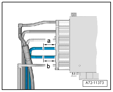
- Disconnect pneumatic lines to the backrest bolster inflation adjuster air cushions at the following points (refer to → Chapter "Pneumatic Lines, Disconnecting and Connecting"):
- a - 40 mm
- b - 40 mm
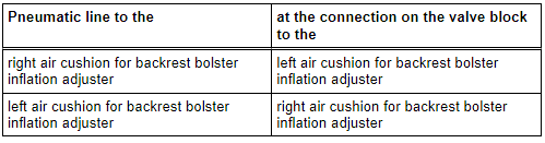
- For checking in the "Guided Fault Finding", connect the air cushion and valve block connections in a diagonal sequence as follows:
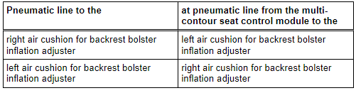
- To connect, attach the Connecting Sleeves -VAS6618/3- to the pneumatic lines.
Note
- To connect, insert the pneumatic lines into the Connecting Sleeves -VAS6618/3- from both sides in direction of -A arrows-.
- Because of the danger of leaks, do not place the connecting sleeves in a bend in the hose.
- To release, push release rings in direction of -B arrows- and simultaneously remove pneumatic lines in direction of -C arrows-.
- Connect pneumatic lines following the leak check. Refer to → Chapter "Pneumatic Lines, Disconnecting and Connecting".
Preparations for Checking the Backrest Bolster Inflation Adjustment for Leaks, from 09/2012
Special tools and workshop equipment required
- Vehicle Diagnostic Tester
Note
- When an appropriate entry is made in the event memory, you are prompted in "Guided Fault Finding" to perform a leak check using the Vehicle Diagnostic Tester.
- Then the preparations for this leak test are described that must be carried out directly in the front seat.
- For the connection diagram with assignment of the pneumatic lines to the air cushions. Refer to → Chapter "Connection Diagram - Pneumatic System".
Procedure
- Remove the backrest cover. Refer to → Chapter "Backrest Cover, Removing and Installing, Multi-contour Seat".
- Before disconnecting, mark the pneumatic line assignments to the connections at the valve block using a waterproof permanent marker.
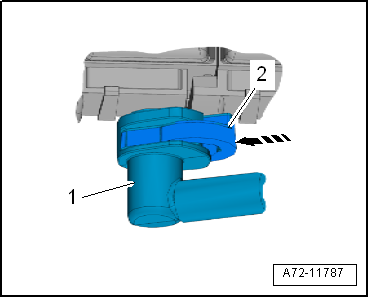
- Disconnect the pneumatic lines -1 and 2- to the backrest bolster adjuster air cushions.
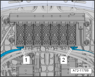
- To do this, press the release mechanism -2--arrow- and simultaneously remove the pneumatic line -1-.
- Free up the pneumatic lines.
- For checking in the "Guided Fault Finding", connect the air cushion and valve block connections in a diagonal sequence as follows:
- Connect the pneumatic lines and check them with a final tug, whether the coupling is locked in correctly.
Preparations for Checking the Massage Mat Air Cushion for Leaks, through 08/2012
Special tools and workshop equipment required
- Pneumatic Repair Set -VAS6618A-
- Vehicle Diagnostic Tester
Note
- When an appropriate entry is made in the event memory, you are prompted in "Guided Fault Finding" to perform a leak check using the Vehicle Diagnostic Tester.
- Then the preparations for this leak test are described that must be carried out directly in the front seat.
- For the connection diagram with assignment of the pneumatic lines to the air cushions. Refer to → Chapter "Connection Diagram - Pneumatic System".
Procedure
- Remove the backrest cover. Refer to → Chapter "Backrest Cover, Removing and Installing, Multi-contour Seat".
- Before disconnecting, mark the assignment of the pneumatic lines to each other using a waterproof permanent marker.
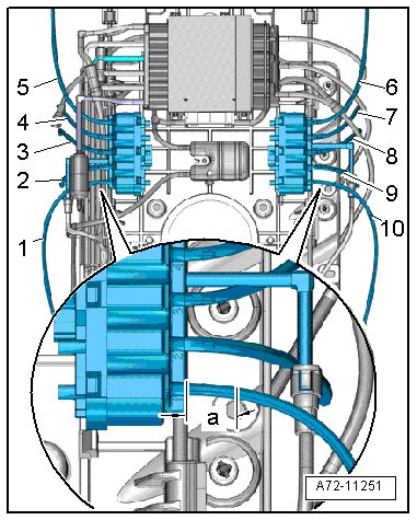
- Disconnect pneumatic lines -1 through 10- to all air cushions of the massage mat at the following points (refer to → Chapter "Pneumatic Lines, Disconnecting and Connecting"):
- a - 40 mm
- To check in the "Guided Fault Finding", detach both valve blocks at the module carrier (refer to → Chapter "Multi-contour Seat Valve Block, Removing and Installing") and connect them to the pneumatic lines on the respective opposite side.
- To connect, attach the Connecting Sleeves -VAS6618/4- to the pneumatic lines.
- Connect the connectors.
Note
- To connect, insert the pneumatic lines into the Connecting Sleeves -VAS6618/4- from both sides -A arrows-.
- To release, push release rings in direction of -B arrows- and simultaneously remove pneumatic lines in direction of -C arrows-.
- In one of the test steps in the "Guided Fault Finding", you are prompted to disconnect the connectors at the solenoid valve blocks and connect them in diagonal sequence by releasing the solenoid valve blocks from the module carrier where required.
- Connect pneumatic lines following the leak check. Refer to → Chapter "Pneumatic Lines, Disconnecting and Connecting".

