Audi A6 Typ 4G: Preparations for Checking the Massage Mat Air Cushion for Leaks, from 09/2012
Special tools and workshop equipment required
- Pneumatic Repair Set -VAS6618A-
- Vehicle Diagnostic Tester
 Note
Note
- When an appropriate entry is made in the event memory, you are prompted in "Guided Fault Finding" to perform a leak check using the Vehicle Diagnostic Tester.
- Then the preparations for this leak test are described that must be carried out directly in the front seat.
- For the connection diagram with assignment of the pneumatic lines to the air cushions. Refer to → Chapter "Connection Diagram - Pneumatic System".
Procedure
- Remove the backrest cover. Refer to → Chapter "Backrest Cover, Removing and Installing, Multi-contour Seat".
Note
- To check, the pneumatic line from the compressor is not disconnected at the connection, but is disconnected by the described procedure. Refer to → Chapter "Pneumatic Lines, Disconnecting and Connecting".
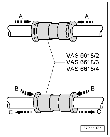
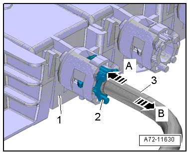
- To connect during the leak test, insert the pneumatic lines into the Pneumatic Repair Set - Exterior Connector 6x4 -VAS6618/2- from both sides -A arrows-.
- To release, push release rings in direction of -B arrows- and simultaneously remove pneumatic lines in direction of -C arrows-.
Driver Side
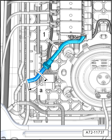
- Disconnect the pneumatic line -1- from the compressor at the following locations:
a - 30 mm
Front Passenger Side
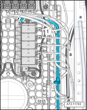
- Disconnect the pneumatic line -1- from the compressor at the following locations:
a - 315 mm
Continuation
- Disconnect the connector -6-.
- Before disconnecting, mark the pneumatic line assignments to the connections at the valve block using a waterproof permanent marker.
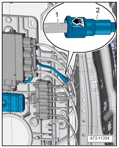
- Disconnect the pneumatic lines -1 through 5- from all of the massage mat air cushions.
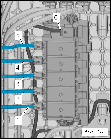
- To do this, press the release ring -2- in valve block -1- direction of -arrow A- and at the same time pull out the pneumatic line -3- in direction of -arrow B-.
- Repeat the procedure on the opposite valve block.
- To check in the "Guided Fault Finding", detach both valve blocks at the module carrier (refer to → Chapter "Multi-contour Seat Valve Block, Removing and Installing") and connect them to the pneumatic lines on the respective opposite side.
- Connect the connectors.
- In one of the test steps in the "Guided Fault Finding", you are prompted to disconnect the connectors at the solenoid valve blocks and connect them in diagonal sequence by releasing the solenoid valve blocks from the module carrier where required.
- Connect the pneumatic lines and check them with a final tug, whether the coupling is locked in correctly.
Preparations for Compressor and Pressure Line Leak Check, through 08/2012
Special tools and workshop equipment required
- Turbocharger Tester Kit -VAG1397A-
- Pneumatic Repair Set -VAS6618A-
- Vehicle Diagnostic Tester
Note
- When an appropriate entry is made in the event memory, you are prompted in "Guided Fault Finding" to perform a leak check using the Vehicle Diagnostic Tester.
- Then the preparations for this leak test are described that must be carried out directly in the front seat.
- For the connection diagram with assignment of the pneumatic lines to the air cushions. Refer to → Chapter "Connection Diagram - Pneumatic System".
Procedure
- Remove the backrest cover. Refer to → Chapter "Backrest Cover, Removing and Installing, Multi-contour Seat".
- Front seat released in the vehicle and folded forward with electrical harness connectors connected. Refer to → Chapter "Front Seat, Removing and Installing".
Version with a Separate Check Valve and Restrictor on the Multi-contour Seat Control Module:
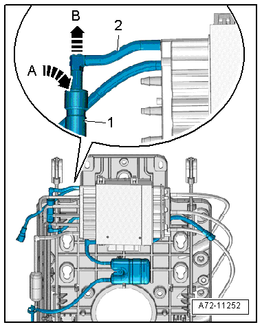
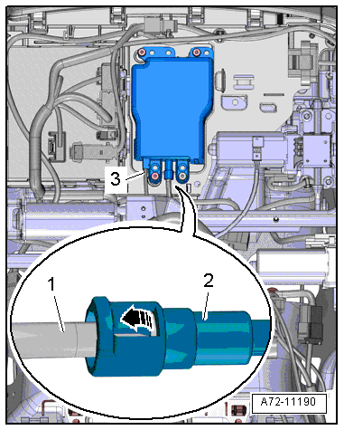
- Disconnect the pneumatic line to the Driver Multi-contour Seat Control Module -J873-/Front Passenger Multi-contour Seat Control Module -J872- by pressing release ring on the check valve -1- in direction of -arrow A- and simultaneously removing the pneumatic line -2- in direction of -arrow B-.
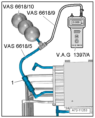
- Using hose and adapter pieces, as well as the Valve Block 1 in Passenger Side Rear Seat -N481-, connect the Turbocharger Tester Kit -VAG1397A- with the pneumatic line coming from the compressor to the check valve -1-.
Version with an integrated check valve and restrictor in the Multi-contour seat control module:
Note
The pneumatic line must be disconnected from the Multi-contour seat control module with an integrated check valve and restrictor. Refer to the Parts Catalog.
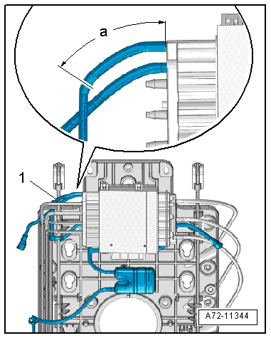
- Disconnect the pneumatic line -1- to the Driver Multi-contour Seat Control Module -J873-/Front Passenger Multi-contour Seat Control Module -J872- at the following location (refer to → Chapter "Pneumatic Lines, Disconnecting and Connecting"):
a - 50 mm
- Using hose and adapter pieces, as well as the Valve Block 1 in Passenger Side Rear Seat -N481-, connect the Turbocharger Tester Kit -VAG1397A- with the pneumatic line coming from the compressor.
- To connect, attach the Connecting Sleeve -VAS6618/3--1- to the pneumatic line.
Continuation for All Versions
Note
- To connect, insert the pneumatic lines into the Connecting Sleeves -VAS6618/3- from both sides -A arrows-.
- To release, push release rings in direction of -B arrows- and simultaneously remove pneumatic lines in direction of -C arrows-.
In one of the test steps in the "Guided Fault Finding", you are prompted to connect the Turbocharger Tester Kit -VAG1397A- at the pneumatic line to the Valve Block 1 in Driver Seat -N475-/Valve Block 2 in Driver Seat -N476- or Valve Block 1 in Front Passenger Seat -N477-/Valve Block 2 in Front Passenger Seat -N478-.
- Carefully release the retainer -arrow- and disconnect the pneumatic lines -1 and 2-.
- Using hose and adapter pieces, as well as the Valve Block 1 in Passenger Side Rear Seat -N481-, connect the Turbocharger Tester Kit -VAG1397A- with the pneumatic line -1- coming from the compressor.
- Repeat the check on the pneumatic line coming from the compressor at the opposing valve block.
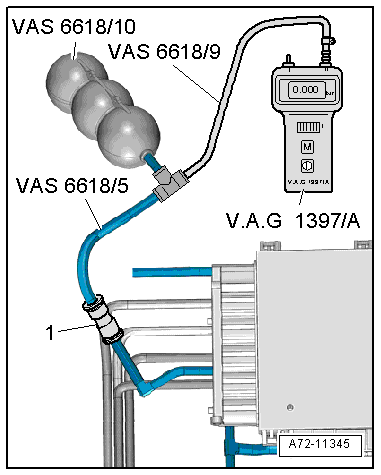
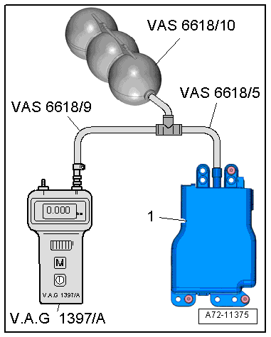
In one of the test steps in the "Guided Fault Finding", you are prompted to connect the Turbocharger Tester Kit -VAG1397A- directly to the compressor.
- Carefully release the retainer -arrow- and remove the pneumatic line -1- from the compressor -2-.
Note
Ignore item -3-.
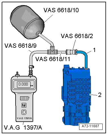
- Using hose and adapter pieces, as well as the Pneumatic Repair Set - Surge Tank -VAS6618/10-, connect the Turbocharger Tester Kit -VAG1397A- with the compressor -1-.
- Connect pneumatic lines following the leak check. Refer to → Chapter "Pneumatic Lines, Disconnecting and Connecting".
Preparations for Compressor and Pressure Line Leak Check, from 09/2012
Special tools and workshop equipment required
- Turbocharger Tester Kit -VAG1397A-
- Hose Cutting Pliers -VAS6228-
- Pneumatic Repair Set -VAS6618A-
- Vehicle Diagnostic Tester
Note
- When an appropriate entry is made in the event memory, you are prompted in "Guided Fault Finding" to perform a leak check using the Vehicle Diagnostic Tester.
- Then the preparations for this leak test are described that must be carried out directly in the front seat.
- For the connection diagram with assignment of the pneumatic lines to the air cushions. Refer to → Chapter "Connection Diagram - Pneumatic System".
Procedure
- Remove the backrest cover. Refer to → Chapter "Backrest Cover, Removing and Installing, Multi-contour Seat".
- Front seat released in the vehicle and folded forward with electrical harness connectors connected. Refer to → Chapter "Front Seat, Removing and Installing".
Note
- To check, the pneumatic line from the compressor is not disconnected at the connection, but is disconnected by the described procedure. Refer to → Chapter "Pneumatic Lines, Disconnecting and Connecting".
- To connect during the leak test, insert the pneumatic lines into the Pneumatic Repair Set - Exterior Connector 6x4 -VAS6618/2- from both sides -A arrows-.
- To release, push release rings -B arrows- and simultaneously remove pneumatic lines -C arrows-.
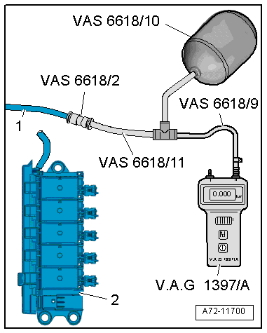
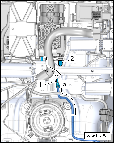
In one of the test steps in the "Guided Fault Finding", you are prompted to connect the Turbocharger Tester Kit -VAG1397A- at the pneumatic line to the Valve Block 2 in Driver Seat - N476-/Valve Block 2 in Front Passenger Seat -N478-.
- Disconnect the pneumatic line -1- from the valve block.
a - 30 mm
- Using hose and adapter pieces from the Pneumatic Repair Set -VAS6618A- as well as the Pneumatic Repair Set - Surge Tank -VAS6618/10-, connect the Turbocharger Tester Kit -VAG1397A- with the pneumatic line -1- coming from the compressor.
2 - Valve Block 2 in Driver Seat -N476-/Valve Block 2 in Front Passenger Seat -N478-
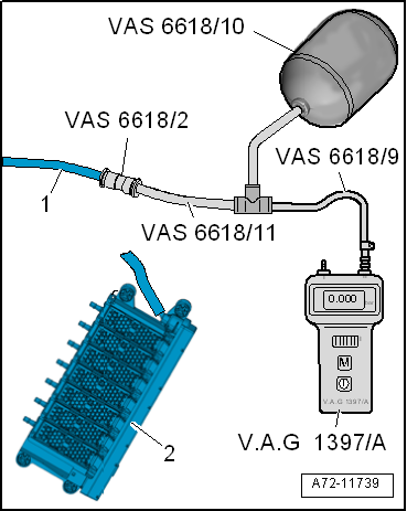
In one of the test steps in the "Guided Fault Finding", you are prompted to connect the Turbocharger Tester Kit -VAG1397A- at the pneumatic line to the Valve Block 3 in Driver Seat -N523-/Valve Block 3 in Front Passenger Seat -N524-.
- Disconnect the pneumatic line -1- from the valve block.
a - 315 mm
- Using hose and adapter pieces from the Pneumatic Repair Set -VAS6618A- as well as the Pneumatic Repair Set - Surge Tank -VAS6618/10-, connect the Turbocharger Tester Kit -VAG1397A- with the pneumatic line -1- coming from the compressor.
2 - Valve Block 3 in Driver Seat -N523-/Valve Block 3 in Front Passenger Seat -N524-
In one of the test steps in the "Guided Fault Finding", you are prompted to connect the Turbocharger Tester Kit -VAG1397A- at the pneumatic line to the Valve Block 1 in Driver Seat - N475-/Valve Block 1 in Front Passenger Seat -N477-.
- Disconnect the pneumatic line -1- from the valve block.
a - 30 mm
- Using hose and adapter pieces from the Pneumatic Repair Set -VAS6618A- as well as the Pneumatic Repair Set - Surge Tank -VAS6618/10-, connect the Turbocharger Tester Kit -VAG1397A- with the pneumatic line -1- coming from the compressor.
2 - Valve Block 1 in Driver Seat -N475-/Valve Block 1 in Front Passenger Seat -N477-
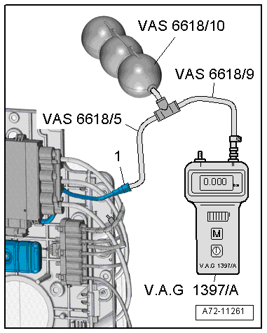
In one of the test steps in the "Guided Fault Finding", you are prompted to connect the Turbocharger Tester Kit -VAG1397A- directly to the compressor.
Note
To check, the pneumatic line from the compressor is not disconnected at the connection, but is disconnected by the described procedure. Refer to → Chapter "Pneumatic Lines, Disconnecting and Connecting".
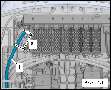
- Disconnect the pneumatic line -1- from the compressor at the following locations:
a - 220 mm
Note
Ignore item -2-.
- Using line and adapter pieces, as well as the Pneumatic Repair Set - Surge Tank -VAS6618/10-, connect the Turbocharger Tester Kit -VAG1397A- with the pneumatic line -1- for the compressor -2-.
Note
To connect the pneumatic lines, make an adapter hose from the Pneumatic Repair Set -VAS6618A-.
- Connect the pneumatic lines and check them with a final tug, whether the coupling is locked in correctly.
Pneumatic Lines, Disconnecting and Connecting
Special tools and workshop equipment required
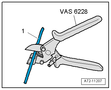
- Hose Cutting Pliers -VAS6228-
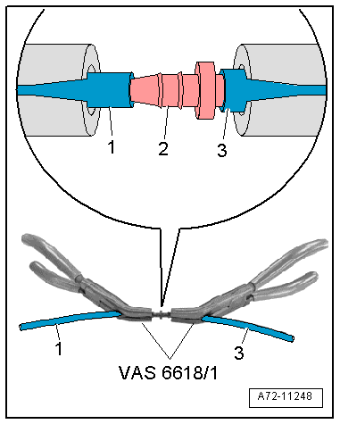
- Pneumatic Repair Set - Pliers -VAS6618/1- (quantity: 2)
Cutting Pneumatic Lines
- Position the Hose Cutting Pliers -VAS6228- at a right angle and cut the pneumatic line -1-.
Connecting Pneumatic Line
- Slide the pneumatic lines -1 and 3- onto the line connector -2- on both sides using the Pneumatic Repair Set - Pliers -VAS6618/1-. Refer to the Parts Catalog.
Pneumatic Lines, Servicing
- A repair kit with pneumatic lines and line connectors is available for the repair of pneumatic lines. Refer to the Parts Catalog.
- Pneumatic lines must not be disconnected directly at the components, only disconnection and connection according to the methods described below is permissible.
- Original replacement parts are delivered with short sections of line to which pneumatic lines with line connectors are connected.
- Protect pneumatic lines and line connectors from soiling.
- Heating the pneumatic lines to connect them to the line connectors is NOT permissible.
- The use of lubricant to connect the pneumatic lines to the line connectors is NOT permissible.
- The repaired pneumatic line is to be exactly as long as the previous line - tolerance +- 10 mm.
- Dirt on the connecting points can cause leaks. Therefore, during tests, make sure the pneumatics and the measuring instruments remain clean.

