Audi A6 Typ 4G: Wheels/Tires/Tire Pressure Monitoring Assembly
Wheels and Tires, General Information
Only install tires with the same manufacturer, construction type and tread on all wheels.
Always replace rubber valve when replacing steel wheel or rim.
Install tires with DOT identification facing toward outside of wheel. Only applies to left side of vehicle with directional tires.
With directional tires, a wheel/tire combination for the right side should be installed as a spare wheel.
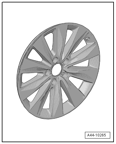
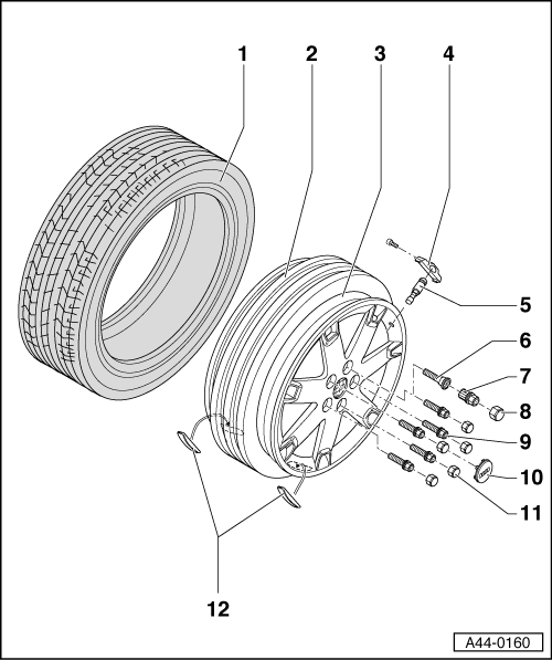
Light Alloy Wheels Component Overview
 Note
Note
- Be careful not to scratch off the glued- on wheel trim on these rims.
- The surface of the wheel trim is very sensitive.
- The rim will have be replaced if the wheel trim is damaged.
- The wheel trim cannot be replaced.
Light alloy wheels assembly overview.
Changing/mounting wheel, assembly information. Refer to → Chapter "Wheel, Changing and Mounting".
1 - Tires
2 - Valve
- Always replace
- Only install valve according to the Parts Catalog
3 - Wheel
- Note assembly instructions. Refer to → Chapter "Wheel, Changing and Mounting"
4 - Wheel Bolt
- Note assembly instructions. Refer to → Chapter "Wheel, Changing and Mounting"
- Anti-theft wheel bolts. Refer to → Fig. "Anti-Theft Wheel Bolts"
5 - Wheel Bolt Adapter
- Place on wheel bolt designed for it. Refer to → Fig. "Anti-Theft Wheel Bolts"
6 - Wheel Bolt Cover Cap
7 - Cap
8 - Wheel Bolt
Note
Make sure the correct wheel bolts are installed. Refer to the Parts Catalog
- Note assembly instructions. Refer to → Chapter "Wheel, Changing and Mounting"
9 - Adhesive Balancing Weights
- Maximum 60 grams per rim flange permitted
- Clean wheel where it will be adhered so it is free of dirt and grease
- Remove protective film
- Attach balance weights to intended surfaces
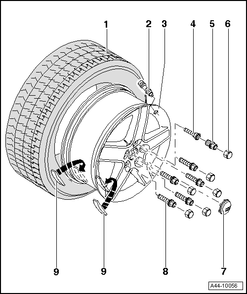
Component Overview - Run-Flat Tire (PAX)
 Caution
It is mandatory for run-flat tires to have a tire pressure monitoring system in the vehicle.
Note
- Be careful not to scratch off the glued- on wheel trim on these rims.
- The surface of the wheel trim is very sensitive.
- The rim will have be replaced if the wheel trim is damaged.
- The wheel trim cannot be replaced.
1 - PAX Tires
2 - Support Ring
3 - Wheel for PAX Tires
- Note assembly instructions. Refer to → Chapter "Wheel, Changing and Mounting"
4 - Wheel Electronics
- Batteries must be completely replaced.
- Remaining battery life, temperature and pressure can be read via diagnosis with Vehicle Diagnostic Tester.
Beru wheel electronics system. Refer to → Chapter "Wheel Electronics System (Tire Pressure Monitoring System), Beru".
Siemens wheel electronics system. Refer to → Chapter "Wheel Electronics System (Tire Pressure Monitoring System), Siemens ".
5 - Metal Valve Body
- Only install valve according to Parts Catalog
- Delivered complete
6 - Wheel Bolt
Note
Make sure the correct wheel bolts are installed. Refer to the Parts Catalog.
- Note assembly instructions. Refer to → Chapter "Wheel, Changing and Mounting"
- Anti-theft wheel bolts. Refer to → Fig. "Anti-Theft Wheel Bolts"
7 - Wheel Bolt Adapter
- Place on wheel bolt designed for it. Refer to → Fig. "Anti-Theft Wheel Bolts"
8 - Cap
- Place on wheel bolt
9 - Wheel Bolt, Two-Part
- Note assembly instructions. Refer to → Chapter "Wheel, Changing and Mounting"
10 - Cap
11 - Wheel Bolt Cover Cap
12 - Adhesive Balancing Weights
- Maximum 60 grams per rim permitted
- Clean wheel where it will be adhered so it is free of dirt and grease
- Remove protective film
- Attach balance weights to intended surfaces
Wheel, Changing and Mounting
Special tools and workshop equipment required
- Torque Wrench 1332 40-200Nm -VAG1332-
- Wheel Lock Set -T10101-
- Wheel Lock Set -T10101A-
- Wheel Lock Set -T40004-
- Wheel Lock Set -T40073-
- Wax Spray -D 322 000 A2-
- Optimol TA Paste -G 052 109 A2-
Note
The wrench size of the included wheel bolt adapter can be vary from the wrench size of the respective master set.
Wheel, Changing
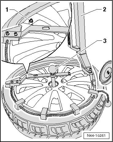
Caution
If brake pads are ceramics, wheel must not fall on brake disc, otherwise it will be irreparably damaged. To remove/mount a wheel, install the long assembly pin instead of wheel bolts at the top position (12 o'clock position) and insert the short assembly pin in the wheel bolt mounts for support. In this way, the wheel can glide on the assembly aids when removing/installing.
Note
- Only raise vehicle at designated mounting points.
- On vehicles with alloy wheels, do not pry out cover caps with a screwdriver but rather use only the special tool designed for this (puller hook in vehicle tool kit).
- To loosen wheel bolts, use sockets in the correct size. Sockets that did not fit must not be used any more.
- Do not use an impact wrench to loosen anti-theft wheel bolts (lockable wheel bolts).
- Do not make wheel bolts dirty.
 DANGER!
The secure seating of the wheel bolts and the wheels is only ensured if the instructions and checks below are followed.
The following checks and instructions must be performed with wheel (rim) removed!
DANGER!
In order to make sure the wheel bolts fit correctly, be use to use the correct wheel bolts specified for the model. The wheel bolts for each model have different diameters on the surface of the ball running surface on the wheel rim and they have different lengths.
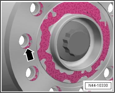
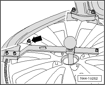
- Check if the contact surfaces -arrows- between the brake disc/wheel hub brake disc/brake drum and the wheel (rim) are free of corrosion and dirt.
- If necessary, remove oil, grease, grease and corrosion.
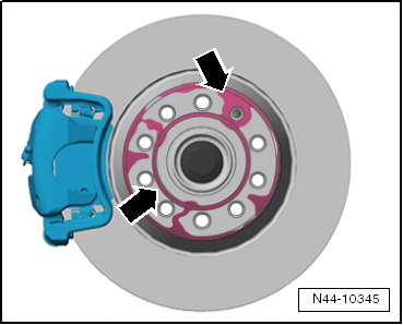
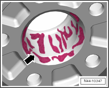
- Make sure there is no corrosion or dirt on the center of the wheel hub -arrows-.
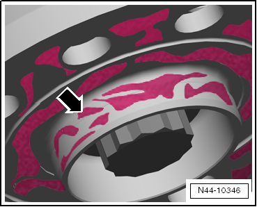
- Make sure the contact surfaces -arrow- on the wheel inner side (rim) as well as the central seat in the rim is free of corrosion and dirt.
- The spherical caps in the wheel bolt holes must not have any corrosion, dirt, oil or grease on them.
- If necessary, remove oil, dirt and corrosion and reapply corrosion protection in centering seat area with Wax Spray -D 322 000 A2-.
Note
- The wax spray must not get onto brake system parts.
- If rust or dirt falls between brake disc and wheel hub during removal, remove it by blowing out with compressed air.
DANGER!
Wear protective eyewear when working with compressed air.
The wheel (rim) spherical caps and wheel bolts must be free of dirt and corrosion.
- Dirty wheel (rim) spherical caps should be cleaned with a lint-free cloth.
- Check wheel bolts and wheel hub threads for cleanliness.
- Clean dirty wheel bolts in spherical cap area and threads, for example, with a brass brush.
WARNING
Heavily corroded or damaged wheel bolts must be replaced.
If lightly corroded wheel bolts are reused, they must be cleaned in area of spherical cap and threads and Optimol AT -G 052 109 A2- paste must be applied to slide surfaces as follows (all vehicles except RS 2 and RS 4, type 8D):
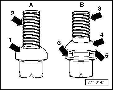
A - One-part wheel bolt. Lightly lubricate threaded area -2- and spherical cap -1-.
B - Two-part wheel bolt. Lightly lubricate threaded area -3- as well as between bolt head contact surface -6- and spherical cap ring -5-. The spherical cap to wheel (rim) contact surface -4- must not be lubricated.
Note
Only use Optimol TA -G 052 109 A2- paste. The paste must not get on brake system parts.
Only for RS 2 and RS 4 type 8D:
- Lightly corroded wheel bolts must not be cleaned and lubricated. These wheel bolts should be replaced.
- Install wheel bolts dry.
All Vehicles
- Check whether the wheel bolts can be easily installed by hand without tools. It must be easy to install the wheel bolts the entire length of the threads when installing the wheel.
- Make sure that threads align with the hub. The threads of the wheel bolts must not touch the holes in the brake disc.
- If the thread of the wheel bolt touches the hole, turn the brake disc relative to the wheel accordingly.
Wheel Mounting
Note
- Be careful not to scratch off the glued- on wheel trim on these rims.
- The surface of the wheel trim is very sensitive.
- The rim will have be replaced if the wheel trim is damaged.
Run-Flat Tires, Removing and Mounting
Caution
It is mandatory for run-flat tires to have a tire pressure monitoring system in the vehicle.
Safety Precautions, Run-Flat Tires
Caution
It is mandatory for run-flat tires to have a tire pressure monitoring system in the vehicle.
- Work for removing and mounting tires with emergency running characteristics must only be performed by mechanics specially trained for it.
- The special tools necessary must be in proper working order and not damaged! Contact manufacturer of tire mounting device found in the workshop directly for suitable additional tools. Additional tools are offered as recommended accessories for the tire mounting devices listed with VAS - numbers.
- If necessary, use a mounting paste recommended by the tire manufacturer.
- The description of work procedure for removing and mounting may vary depending on the device manufacturer and type of device.
- The following work procedure described explains the principal procedure for removing and mounting tires with emergency running characteristics. It is important to recognize run-flat tires before starting the removal and mounting process as it will be different from the process used with standard tires.
- Characteristics: these tires are identified with the following abbreviations: DSST, Euforia, RFT, ROF, RSC, SSR or ZP. These abbreviations are located on the tire flank behind tire designation of the respective tire manufacturer.
- Always note the instructions and danger warnings identified in the following description!
- Check whether tire pressure sensor should be replaced (if equipped) the Vehicle Diagnostic Tester.
Note
- During removal and mounting work, make sure that no contact is made between tires and tire pressure sensor.
- When cleaning disc wheel (rim), tire pressure monitor sensor must not come into contact with water or be blown with pressurized air.
Installation Instructions, Run-Flat Tires
Warm up cold tires to the minimum mounting temperature
Note
This applies also to ultra high performance tires (height-/width ration smaller/same 45% and speed rating symbol larger than/same as V).
WARNING
The minimum mounting temperature for a tire may not be below 21℃ or above 30℃.
- For injury-free mounting, the upper sidewall and the upper bead inside must be minimum 15º C (59º F).
- The internal temperature is called the core temperature.
- Rubber is a poor heat conductor, and for this reason, a cold tire must be within a temperature-controlled environment for a sufficient amount of time until the inner rubber layers have warmed up to at least 21ºC (70ºF).
- The tire surface temperature during the warm-up phase is not a measure the inside temperature.
- So that the cold tires warm up as quickly as possible, never stack them one on top of the other; store them separated from each other so that the warm air can "circulate" around them.
- Never us a room heater or a hot air gun to warm up tires because the surface temperature will heat up very quickly to a critical temperature.
- To prevent damage, only warm water or warm air (maximum 50º C (32º F) (122º F)) can be used to warm up a tire!
- If cold tires (below 0º C (32º F)) are brought into a warm room (above 0º C (32º F)), a layer of ice will start to form on the tires. This layer of ice means that humidity in the warm air is condensing on the tire.
- Once the layer of ice starts to melt, wipe up the water with a rag so that the warming up process will not be slowed down.
Warm-Up Time:
- Using the example of a room temperature of at least 19º C (66º F) and a tire temperature of 0º C (32º F) or higher, the tires should be stored for at least two hours at least 19º C (66º F).
- If the room temperature is minimum 19º C (66º F) and the tire temperature is below 0º C (32º F) , then the tires should be stored for at least 2.5 hours at a minimum room temperature of 19º C (66º F).
Recommendations:
- If possible, let the tires stand in the workshop for one day before mounting them.
- Store the tires as high as possible on an insulated surface, pallet or something similar.
- Position the tires so that they can be "surrounded" by the warm air.
- Wipe off the sweat.
- Never heat the tires with a room heater or a hot air gun!
WARNING
The minimum mounting temperature for a tire may not be below 21ºC (70ºF) or above 30℃. (86 ºF)
Pressing Off Tires, Run-Flat Tires
- Release air from tires, unscrew the valve insert to do so.
Note
- Be careful not to scratch off the glued- on wheel trim on these rims.
- The surface of the wheel trim is very sensitive.
- The rim will have be replaced if the wheel trim is damaged.
- The wheel trim cannot be replaced.
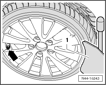
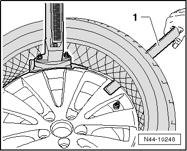
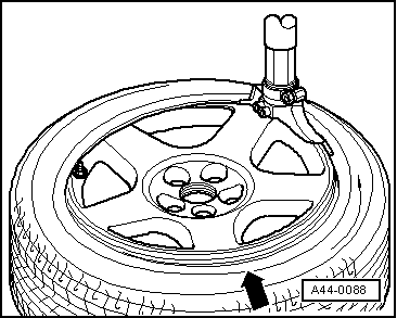
- When pressing off tire on a tire dismounting/mounting machine with press-off blade, always make sure that tire valve/tire pressure sensor -arrow- is located opposite the press-off blade -1-.
Press-off blade must be applied at maximum 2 cm removed from rim flange.
- Remove balancing weights and coarse dirt from disc wheel.
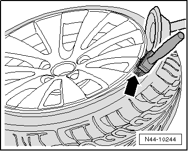
- Press off both tire beads around circumference while thoroughly applying tire mounting paste between tire and rim flange -arrow-.
Removing Tires, Run-Flat Tires
Note
- Be careful not to scratch off the glued- on wheel trim on these rims.
- The surface of the wheel trim is very sensitive.
- The rim will have be replaced if the wheel trim is damaged.
- The wheel trim cannot be replaced.
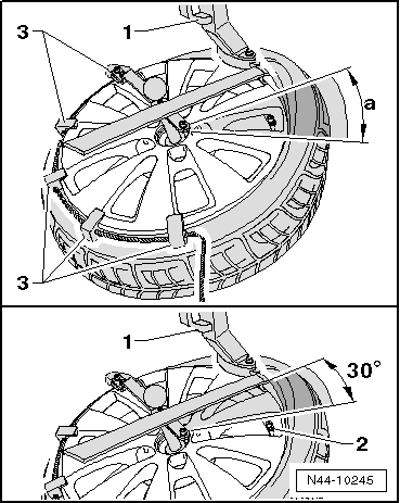
- Turn wheel on tire mounting device so that tire valve/tire pressure sensor -2- stands in front of mounting head -1-.
Caution
Mounting head -1- must not be located in area -a- of tire valve/tire pressure sensor, otherwise the mounting head will damage the tire pressure sensor.
- Position mounting head -1- in vicinity of tire valve/tire pressure sensor so that tire iron can be put on approximately 30º next to tire valve/tire pressure sensor -2-.
- Install press holders -3- on disc wheel opposite the mounting head -1-.
- Now pry tire bead over mounting finger on mounting head using tire iron and remove tire iron again.
- Let the tire dismounting/mounting machine run clockwise until upper bead lies completely above the rim flange.
This slides the press holders -1- against the mounting head. This allows them to be removed again easily.
- Turn wheel on tire mounting device so that tire valve/tire pressure sensor -2- stands in front of mounting head -1-.
Caution
Mounting head -1- must not be located in area -a- of tire valve/tire pressure sensor, otherwise the mounting head will damage the tire pressure sensor.
- Position mounting head -1- in vicinity of tire valve/tire pressure sensor so that tire iron can be put on approximately 30º next to tire valve/tire pressure sensor -2-.
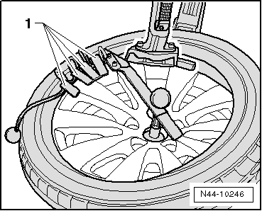
- Now pry tire bead over mounting finger of mounting head using tire iron -3-.
- In addition, insert a plastic mounting lever -4-.
- Remove tire iron -3- again.
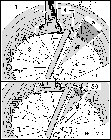
- Using plastic mounting lever -1-, hold bead in place over the rim flange from outside and let tire mounting device run clockwise until tire has been pulled off completely from disc wheel.
Note
- Check tire pressure sensor for loose or damaged parts. If threaded connections are loose, union nut, valve insert, seal, sealing washer and valve cap must be replaced by new parts from repair set Parts Catalog.
- If tire pressure sensor is damaged, then it must be replaced completely.
Tires, Mounting, Run-Flat Tires
Caution
It is mandatory for run-flat tires to have a tire pressure monitoring system in the vehicle.
- Coat rim flanges, tire beads and inside of upper tire beads thoroughly with tire mounting paste.
WARNING
The minimum mounting temperature for a tire may not be below 21ºC (70ºF) or above 30℃. (86 ºF)
Note
- Be careful not to scratch off the glued- on wheel trim on these rims.
- The surface of the wheel trim is very sensitive.
- The rim will have be replaced if the wheel trim is damaged.
- The wheel trim cannot be replaced.
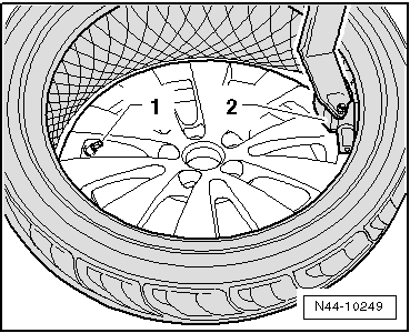
- Turn disc wheel on tire mounting device so that tire valve/Tire Pressure Sensor-1- stands on opposite side of mounting head -2-.
- Let the tire dismounting/mounting machine run clockwise.
WARNING
The minimum mounting temperature for a tire may not be below 21℃ or above 30℃.
Note
- Be careful not to scratch off the glued- on wheel trim on these rims.
- The surface of the wheel trim is very sensitive.
- The rim will have be replaced if the wheel trim is damaged.
- The wheel trim cannot be replaced.
- Mounting of the lower bead ends before the tire valve/Tire Pressure Sensor-arrow- to prevent damage to Tire Pressure Sensor.
Tire bead now slips over the rim flange. Wheel may be turned only as far until mounting head is located just in front of tire valve/Tire Pressure Sensor-arrow-.
- Turn disc wheel on tire mounting device so that tire valve/Tire Pressure Sensor-1- stands on opposite side of mounting head -2-.
- Install press holders -3- on disc wheel.
- Make sure the tire bead is seated correctly on the mounting head and run the mounting machine clockwise.
- Mounting of the upper bead ends before the tire valve/Tire Pressure Sensor-arrow- to prevent damage to Tire Pressure Sensor.
Tire bead now slips over the rim flange. Wheel may be turned only as far until mounting head is located just in front of tire valve/Tire Pressure Sensor-arrow-.
- Remove press holders from rim flange.
- Inflate the tire to a inflation pressure of maximum 3.3 bar (bounce pressure).
Caution
If tire beads do not make contact completely on disc wheel edge, pressure must not be increased under any circumstances.
Pre-damage to tire or disc wheel would result.
- If tire beads do not make contact completely on disc wheel edge, then release air, press off tire bead once more and coat rim flange thoroughly again with tire mounting paste.
- Inflate the tire to a inflation pressure of maximum 3.3 bar (bounce pressure).
- If tire beads make contact on bead seat without problems, then increase inflation pressure to 4 bar to "settle" tire.
- Screw on a new valve insert and fill the tires to the specified pressure.
- Then balance wheel.
- Install the wheel and tighten it to tightening specification.
Overview - Tire Pressure Monitoring System
Caution
It is mandatory for run-flat tires to have a tire pressure monitoring system in the vehicle.
Beru wheel electronics system. Refer to → Chapter "Wheel Electronics System (Tire Pressure Monitoring System), Beru ".
Siemens wheel electronics system. Refer to → Chapter "Wheel Electronics System (Tire Pressure Monitoring System), Siemens ".
Direct Measurement Systems according to Vehicle Model. Refer to → Chapter "Metal Valve Body, Removing and Installing".
Indirect Measurement Systems according to Vehicle Model. Refer to → Chapter "Metal Valve Body, Removing and Installing".
Note
Which system is installed can be identified on the wheel electronics label.
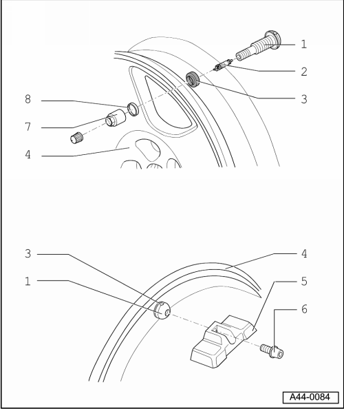
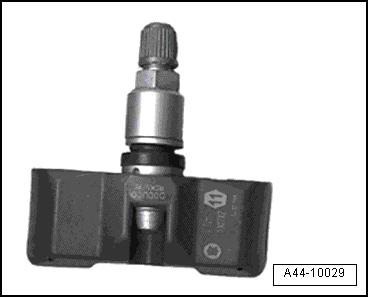
1 - Metal Valve Body
- Refer to the Parts Catalog for the allocation of the only valves to be installed.
- delivered complete
- Replace valve insert with every tire change
- Removing and Installing. Refer to → Chapter "Metal Valve Body, Removing and Installing".
2 - Valve Insert
3 - Seal
- Removing and Installing. Refer to → Chapter "Metal Valve Body, Removing and Installing".
Note
Depending on the model, it is not separable from the valve. Refer to Parts Catalog
4 - Rim
- All models: 4 Nm
- Tires, Dismounting and Mounting. Refer to → Fig. "Dismounting Tire"
Run-Flat Tires, Dismounting. Refer to → Chapter "Removing Tires, Run-Flat Tires"
5 - Wheel Electronics
- Batteries must be completely replaced.
- Remaining battery life, temperature and pressure can be read via diagnosis using the Vehicle Diagnostic Tester.
- Beru Wheel Electronics System, Installing. Refer to → Chapter "Wheel Electronics System (Tire Pressure Monitoring System), Beru ".
- Siemens Wheel Electronics System, Installing. Refer to → Chapter "Wheel Electronics System (Tire Pressure Monitoring System), Siemens ".
Note
Which system is installed can be identified on the wheel electronics label.
WARNING
If tire sealant was used, then the wheel electronics on that particular wheel must be replaced.
WARNING
Damaged wheel electronics must be replaced.
6 - Microencapsulated Screw
Note
Only used on Beru systems
All Models: 4 Nm
- Replacing the bolt
- can only be obtained as a replacement part with wheel electronics
7 - Union Nut
- Removing and Installing. Refer to → Chapter "Metal Valve Body, Removing and Installing".
- Tightening specification. Refer to → Chapter "Metal Valve Body, Removing and Installing".
8 - Beveled Washer
Tires, Changing
The valve insert must be replaced with every tire change.
Metal valve and wheel electronics can be reused.
- Let air out of tire by removing the valve insert.
Note
- Be careful not to scratch off the glued- on wheel trim on these rims.
- The surface of the wheel trim is very sensitive.
- The rim will have be replaced if the wheel trim is damaged.
- The wheel trim cannot be replaced.
- Tires, dismounting. Refer to → Fig. "Dismounting Tire".
Removing Run-Flat Tires. Refer to → Chapter "Removing Tires, Run-Flat Tires".
- Perform a visual inspection for loose or damaged parts. If there are loose threaded connections, replace entire valve unit.
Note
Damaged wheel electronics must be replaced.
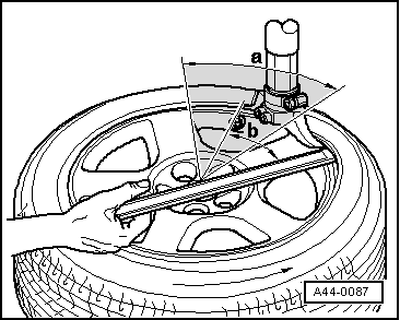
Dismounting Tire
Roll or press tires off.
When using pressure paddles, first separate tires from side opposite of valve.
Note
Do not use pressure paddles in hatched area -a-.
- Position mounting head near valve so that so that tire iron can be put on approximately 30º -b- next to tire valve.
- Then remove tire in valve area first.
Installing Run-Flat Tires. Refer to → Chapter "Tires, Mounting, Run-Flat Tires".
Mounting Tire
Do Not Use Pressure Paddles in Valve Area.
Note
- Be careful not to scratch off the glued- on wheel trim on these rims.
- The surface of the wheel trim is very sensitive.
- The rim will have be replaced if the wheel trim is damaged.
- The wheel trim cannot be replaced.
- Position wheel electronics approximately 180º opposite of mounting head.
- Press tire in bed approximately 90º in front of mounting head -arrow-.
- Install a new valve insert.
- Mount tire.
- Fill tires, reinstall plastic cap.
- Balance tires.
- Install wheel.
Metal Valve Body, Removing and Installing
Special tools and workshop equipment required
- Torque Wrench 1410 -VAG1410- and Torque Wrench 1331 5-50Nm -VAG1331- 11 mm.
- Place metal valve with rubber seal through rim from inside.
- Attach chamfered washer and union nut from outside and tighten by hand.
- Tighten the union nut.
Note
- Be careful not to scratch off the glued- on wheel trim on these rims.
- The surface of the wheel trim is very sensitive.
- The rim will have be replaced if the wheel trim is damaged.
- The wheel trim cannot be replaced.
.png)
.png)
All other models: 4 Nm
1) TPMS direct measuring. The wheel electronics are installed inside the wheel on the metal valve; the tire pressure and temperature values are transmitted and evaluated periodically.
2) TPMS + indirect measuring. There are no wheel electronics installed inside the wheel. With the help of the ABS sensors, the TPMS compares the speed and rolling circumference of the individuals wheels. The loss of pressure is determined indirectly. If there is a change in the tire pressure, then the speed and the rolling circumference of wheel will also change.
3) TPMS indirect measuring. There are no wheel electronics installed inside the wheel. With the help of the ABS sensors, the TPMS compares the rolling circumference of the individual wheels. The loss of pressure is determined indirectly. If there is a change in the tire pressure, then the speed of the tire will also change.
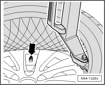
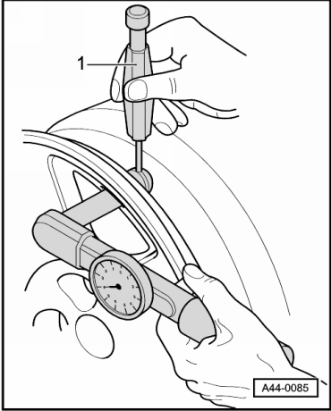
- Secure against turning with counterhold -1- (for example, a 2 mm drill bit).
Note
- Be careful not to scratch off the glued- on wheel trim on these rims.
- The surface of the wheel trim is very sensitive.
- The rim will have be replaced if the wheel trim is damaged.
- The wheel trim cannot be replaced.
Wheel Electronics System (Tire Pressure Monitoring System), Beru
Overview, Beru System
WARNING
If tire sealant was used, then the wheel electronics on that particular wheel must be replaced.
WARNING
Damaged wheel electronics must be replaced.
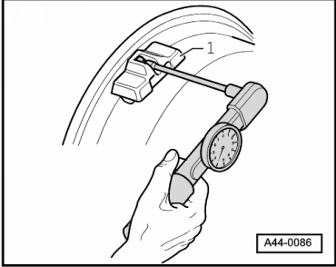
- Push the wheel electronics -1- into the bed.
- Install on the valve from the back with a microencapsulated screw
Note
- Replace the microencapsulated screw.
- Tighten the microencapsulated screw to 4 Nm on all models.
Special tools and workshop equipment required
- Torque Wrench 1410 -VAG1410- and Torque Wrench 1410 Insert - Accessory Kit-VAG1410/1-
Tightening specification for all models: 4 Nm
Wheel Electronics System (Tire Pressure Monitoring System), Siemens
WARNING
If tire sealant was used, then the wheel electronics on that particular wheel must be replaced.
- The Siemens wheel electronics does not have a microencapsulated screw.
- A union nut holds the wheel electronics in place inside the rim -item 7-.
- The metal valve body serves as an antenna.
- The connection between the metal valve body to the wheel electronics must not get damaged.
WARNING
Counterhold the metal valve from the back by hand when pressing the wheel electronics into the bed on the rim. The connection between the metal valve to the wheel electronics must not get interrupted or damaged. Damaged wheel electronics must be replaced.
- Press the wheel electronics into the bed.
- Tighten the wheel electronics to the metal valve with the union nut. Refer to → Chapter "Metal Valve Body, Removing and Installing"
