Audi A6 Typ 4G: Rear Brake Rotor, Removing and Installing
Brake Rotor, Removing and Installing, Steel Brakes
Special tools and workshop equipment required
- Torque Wrench 1331 5-50Nm -VAG1331-
Removing
- If the same brake rotor is reinstalled with used brake pads, remove the brake caliper. Refer to → Chapter "Brake Caliper, Removing and Installing, Steel Brakes".
- If the brake pads and rotor are being replaced, remove the brake pads. Refer to → Chapter "Brake Pads, Removing and Installing, Steel Brakes".
- Loosen the bolt -1- and remove the brake rotor.
Installing
- Check the brake rotors for wear and damage before reusing them:
- Brake rotor wear limit. Refer to → Chapter "Technical Data, Brakes".
 Note
Note
- Always replace brake rotors on both sides of the axle.
- Brake pads likewise must be replaced on both sides of the axle.
 WARNING
Health Risk.
Do not blow out brake system with compressed air.
Note
Use only mineral spirits to clean the brake caliper.
- Thoroughly clean the brake rotor and hub contact surfaces and clear them of corrosion.
- Place the brake rotor on the wheel hub.
Note
Do not tilt the brake rotor when mounting it on the wheel hub.
- Tighten the bolt -1-.
- Install the brake caliper or brake pads.
WARNING
Risk of accident!
- With the vehicle stationary, firmly press the brake pedal several times so that the brake pads in the operating condition properly sit in their respective position.
- Make sure the brakes are working correctly before driving the vehicle for the first time.
Brake Rotor, Removing and Installing, Ceramic Brakes
Special tools and workshop equipment required
- Torque Wrench 1331 5-50Nm -VAG1331-
Removing
- If the same brake rotor is reinstalled with used brake pads, remove the brake caliper. Refer to → Chapter "Brake Caliper, Removing and Installing, Ceramic Brakes".
- If the brake pads and rotor are being replaced, remove the brake pads. Refer to → Chapter "Brake Pads, Removing and Installing, Ceramic Brakes".
 Caution
Danger of causing damage to the ceramic brake rotor.
- Do not drop the brake rotor.
- Do not remove the brake rotor from the hub with a hammer.
- Do not loosen the brake rotor from the hub by prying.
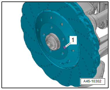
- Remove the bolt -1- and remove the brake rotor by hand. Do not use any tools.
If the brake rotor is seized, do the following:
- Install two M8 bolts -arrows- all the way into the threaded holes of the brake rotor.
- Tighten the bolts 1/2 turn farther alternating from side to side to loosen the brake rotor from the wheel hub.
Installing
Install in reverse order of removal and note the following:
- Check the brake rotors for wear and damage before reusing them:
- Cracks in connection area. Refer to → Chapter "Cracks in Ceramic Brake Rotor Connection Area".
- Chamfer. Refer to → Chapter "Chamfer".
- Nicks. Refer to → Chapter "Nicks on Ceramic Brake Rotor".
- Crack in cooling channel. Refer to → Chapter "Crack in Cooling Channel".
- Brake Rotor Thickness. Refer to → Chapter "Ceramic Brake Rotor, Determining Wear".
Note
- Always replace brake rotors on both sides of the axle.
- Brake pads likewise must be replaced on both sides of the axle.
- When installing brake rotors, pay attention to the arrow showing the direction of travel and to the left and right installed location.
WARNING
Health Risk.
Do not blow out brake system with compressed air.
Note
Use only mineral spirits to clean the brake caliper.
- Thoroughly clean the brake rotor and hub contact surfaces.
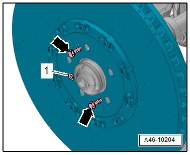
- Tighten the bolt -1-.
Note
Ignore the -arrows-.
- Install the brake caliper or brake pads.
WARNING
Risk of accident!
- With the vehicle stationary, firmly press the brake pedal several times so that the brake pads in the operating condition properly sit in their respective position.
- Make sure the brakes are working correctly before driving the vehicle for the first time.
Rear Brake Shield, Removing and Installing
Removing
- Remove the rear brake rotor. Refer to → Chapter "Brake Rotor, Removing and Installing".
FWD Vehicles:
- Remove the wheel bearing unit. Refer to → Suspension, Wheels, Steering; Rep. Gr.42; Wheel Bearing, Trailing Arm; Wheel Bearing Unit, Removing and Installing.
Continuation for All Vehicles:
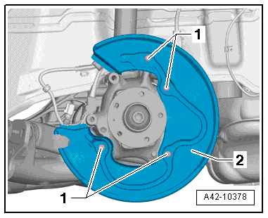
- Remove the cover plate screws -1-.
- Remove the cover plate -2-.
Note
The illustration shows the installation position on an AWD vehicle.
Installing
- Mount the cover plate.
- Install and tighten the cover plate bolts.
FWD Vehicles:
- Install the wheel bearing unit. Refer to → Suspension, Wheels, Steering; Rep. Gr.42; Wheel Bearing, Trailing Arm; Wheel Bearing Unit, Removing and Installing.
Continuation for All Vehicles:
- Install the rear brake rotor. Refer to → Chapter "Brake Rotor, Removing and Installing".
WARNING
Risk of accident!
- With the vehicle stationary, firmly press the brake pedal several times so that the brake pads in the operating condition properly sit in their respective position.
- Make sure the brakes are working correctly before driving the vehicle for the first time.