Audi A6 Typ 4G: Rear Lid Opener Control Module -J938-, Removing and Installing
 WARNING
Risk of leg injury.
Stay outside of the swivel range of the trailer hitch when releasing the trailer hitch.
Removing
- Extend the trailer hitch ball head. Refer to Owner's Manual.
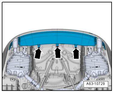
- Remove the bolts -arrows- on the bottom side of the bumper cover.
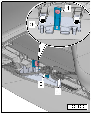
- Disconnect the connectors -1 and 2-.
- Remove the screw -4-.
- Remove the control module -3- from the brackets on the bumper cover -arrows-.
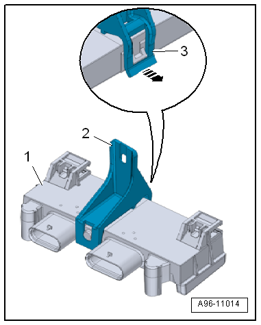
- If the control module is being replaced, release the clip -3--arrow- and disengage the bracket -2- on the control module -1-,
Installing
Install in reverse order of removal.
Tightening Specifications
- Rear bumper. Refer to → Body Exterior; Rep. Gr.63; Rear Bumper; Overview - Bumper Cover.
Power Rear Lid Opener Sensor -G750-/Rear Lid Opener Sensor 2 -G760-, Removing and Installing
Power Rear Lid Opener Sensor -G750-/Rear Lid Opener Sensor 2 -G760-, Removing and Installing, without Trailer Hitch
Removing
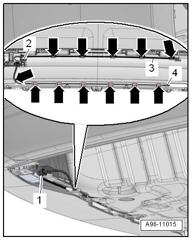
- Remove the bolts -arrows- on the bottom side of the bumper cover.
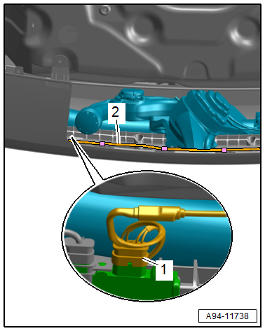
- Remove the mount -1- with the sensor.
- Disconnect the connector -1-.
- Cut through the cable tie -2-.
- Remove the sensors -3 and 4- from the tabs -arrows-.
Installing
Install in reverse order of removal. Note the following:
- The Rear Lid Opener Sensor 2 -G760- must be mounted at the top of the bumper cover.
- How to recognize: Pin "4 and 5" at the connector.
Tightening Specifications
- Rear bumper. Refer to → Body Exterior; Rep. Gr.63; Rear Bumper; Overview - Bumper Cover.
Power Rear Lid Opener Sensor -G750-/Rear Lid Opener Sensor 2 -G760-, Removing and Installing, with Trailer Hitch
Removing
- Remove the bolts -arrows- on the bottom side of the bumper cover.
- Remove the mount -1- with the sensor.
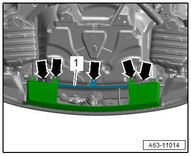
- Disconnect the connector -1-.
- Remove the sensors -2- from the tabs -arrows-.
Installing
Install in reverse order of removal. Note the following:
- The Rear Lid Opener Sensor 2 -G760- must be mounted at the top of the bumper cover.
- How to recognize: Pin "4 and 5" at the connector.
Tightening Specifications
- Rear bumper. Refer to → Body Exterior; Rep. Gr.63; Rear Bumper; Overview - Bumper Cover.