Audi A6 Typ 4G: Suspension Strut, Servicing
Suspension Strut, Servicing, Coil Spring Shock Absorber
Special tools and workshop equipment required
- Spring Compressor Kit - Spring Tensioner -VAG1752/1-
- Spring Compressor Kit - Spring Retainer w/Inserts -VAG1752/6-
- Torque Wrench 1332 40-200Nm -VAG1332-
- Shock Absorber Set -T10001-
Overview
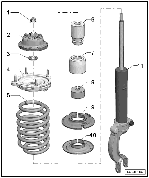
1 - Nut
- 50 Nm
- Always replace if removed
2 - Shock Absorber Mount
3 - Washer
4 - Upper Spring Plate with Spring Support
5 - Coil Spring
6 - Spring
7 - Protective Sleeve
8 - Protective Cap
9 - Lower Spring Support
10 - Lower Spring Plate
11 - Shock Absorber
Shock Absorber with Dynamic Ride Control (DRC) System
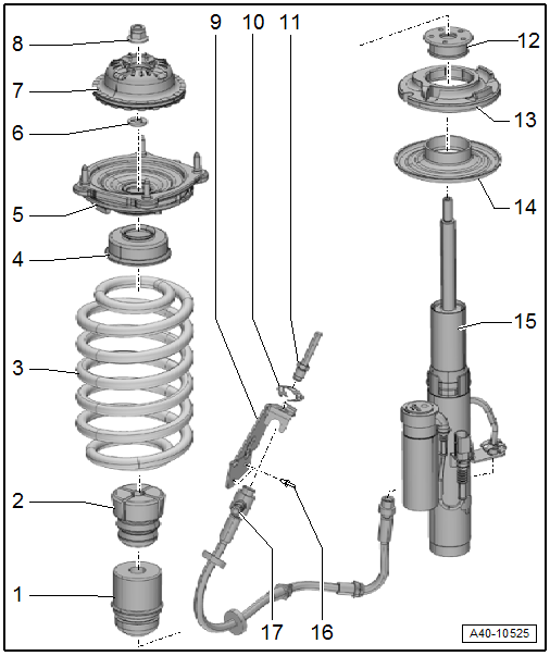
1 - Protective Sleeve
2 - Stop Buffer
3 - Coil Spring
4 - Base Plate
5 - Upper Spring Plate with Spring Support
6 - Washer
7 - Shock Absorber Mount
8 - Nut
- 50 Nm
- Always replace if removed
9 - Bracket
10 - Spring
- Replace if damaged.
11 - Bolt
- 14 Nm
12 - Protective Cap
13 - Lower Spring Support
14 - Lower Spring Plate
15 - Shock Absorber
- For the Dynamic Ride Control (DRC) system
16 - Rivet
17 - Suction/Fill Valve with Hose Line
- Make sure not under tension when installing
Coil Spring, Removing
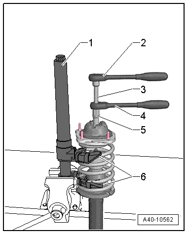
- Place the Spring Compressor Kit - Spring Tensioner -VAG1752/1--1- in the vise.
 Note
Note
To prevent damage to the Spring Compressor Kit - Spring Tensioner -VAG1752/1-, use protective jaws.
- Apply tension to the spring compressor in the Spring Compressor Kit - Spring Tensioner -VAG1752/1- as illustrated.
- Pretension the coil spring in the Spring Compressor Kit - Spring Tensioner -VAG1752/1--1- until the upper spring plate with the spring support are free.
- Remove nut from the piston rod.
- Remove the individual components of the suspension strut and coil spring with the Spring Compressor Kit - Spring Tensioner -VAG1752/1-.
1 - Spring Compressor Kit - Spring Tensioner -VAG1752/1-
2 - Ratchet, commercially available
3 - S hock Absorber Set - Extension SW6 -T10001/7-
4 - Shock Absorber Set - Reversible Ratchet -T10001/11-
5 - Shock Absorber Set - Socket -T10001/3-
6 - Spring Compressor Kit - Spring Retainer w/Inserts -VAG1752/6-
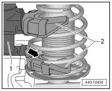
- Make sure the coil spring fits correctly inside the Spring Compressor Kit - Spring Retainer w/Inserts -VAG1752/6--arrow-.
1 - Spring Compressor Kit - Spring Tensioner -VAG1752/1-
2 - Spring Compressor Kit - Spring Retainer w/Inserts -VAG1752/6-
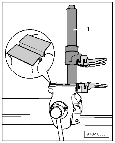
Replacing Shock Absorber
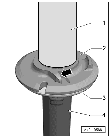
- Remove the cap -1- and the lower spring support -2-.
- Loosen suspension strut -3- using plastic hammer and remove upward.
- Install the spring plate -3- onto the new shock absorber -4- using a rubber hammer.
Installing Coil Spring
- Install the lower spring support and the cap.
- Position the pretensioned coil spring on the lower spring support. End of spring coil must rest against stop -arrow- (permissible play max. 2 mm).
- Position individual suspension strut components.
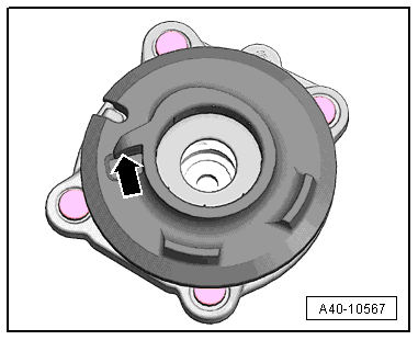
- Install the upper spring plate with spring washer onto pre-loaded spring so that spring washer makes contact on end of spring coil -arrow- (permissible play max. 2 mm).
- Install the shock absorber mounting.
- Tighten the new nut using special tools -Item 1-.
- Release the tension from the Spring Compressor Kit - Spring Tensioner -VAG1752/1- and remove.
Note
Make sure the ends of the spring in the upper and lower spring plates are touching the stops on the spring supports when releasing the tension on the spring compressor.
Suspension Strut, Servicing, Air Spring Damper
Note
Servicing the air spring shock absorber for the time being only involves replacing the boot and cleaning the piston.
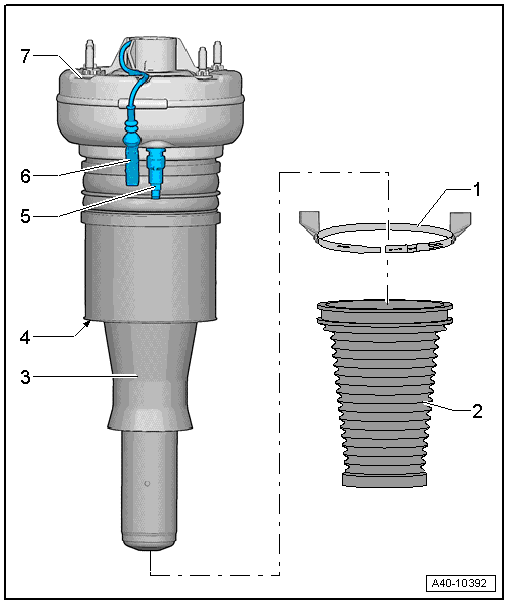
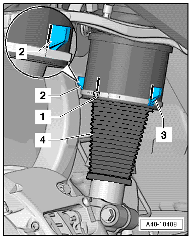
1 - Clamp
- Mark the installed position of the connecting tube and the clips on the air spring shock absorber before removing.
- Always replace if removed
- Tensioning. Refer to → Fig. "Tightening the Clamping Sleeve on the Air Spring Shock Absorber".
2 - Boot
- Must not have any pressure marks; correct any pressure marks by hand.
- Push upward over the collars on the suspension strut housing
3 - Rolling Piston
- Clean if there are contaminants
- Visual inspection. Refer to → Fig. "Visual Inspection"
4 - Rubber Boot
- The surface must be regular and uniform.
- Visual inspection. Refer to → Fig. "Visual Inspection"
5 - Connecting Piece for Air Line with Residual Pressure Retaining Valve
- Tightening specification for the connector: 3 Nm
- Do not loosen the residual pressure retaining valve otherwise the air spring shock absorber will get damaged
6 - Wire
- To the Left Front Damping Adjustment Valve -N336- or Right Front Damping Adjustment Valve -N337-
7 - Air Spring Shock Absorber
- If the Left Front Damping Adjustment Valve -N336- or Right Front Damping Adjustment Valve -N337- is faulty, the entire air spring damper must be replaced.
Special tools and workshop equipment required
- Torque Wrench 1410 -VAG1410-
- Clamping Pliers -VAG1682A-
- Tensioning Strap -T10038-
Removing
Note
Replacement of boot is performed with air spring shock absorber installed.
- Secure the wheel bearing housing using a Tensioning Strap -T10038--1-, as illustrated.
Note
To prevent the joints on the upper control arm from being damaged, support the wheel bearing housing.
- Remove the shock absorber fork. Refer to → Chapter "Shock Absorber Fork, Removing and Installing".
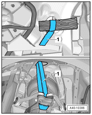
- Unclip the wires from the wire holder -arrow- and free them up.
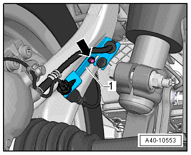
- Remove the bolt -arrow- and remove the bracket -1- brake line and electric wires from the wheel bearing housing.
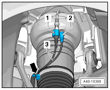
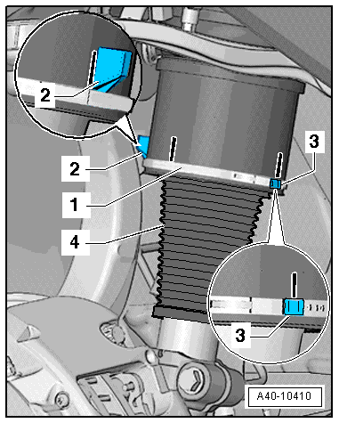
- Mark the position of the connection -1- and of the wire holder -2 and 3- with a felt-tip pen.
- Remove the lock washer -1-.
- Remove the boot -4- carefully off the collar on the suspension strut housing and then pull it down off the rolling piston and off the air spring damper.
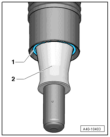
Visual Inspection
Note
Check the surface of the rolling piston and the rubber boot for damage and dirt before installing.
- Check the rubber boot -1- for damage. The surface must be regular and uniform.
- Replace the air spring shock absorber if damaged.
- Check the rolling piston -2- for damage and dirt and clean with surface with sand paper if necessary. Be careful not to make any grooves or scrapes.
Installing
Install in reverse order of removal. Note the following:
- Install the new boot carefully over the collar on the bottom of the rolling piston.
- Install the shock absorber fork. Refer to → Chapter "Shock Absorber Fork, Removing and Installing".
- Lift wheel bearing in control position. Refer to → Chapter "Wheel Bearing in Control Position, Lifting Vehicles with Air Suspension".
- Push the boot -4- over the collar on the top of the suspension strut housing.
- Push the front wire holder -2- onto the clamp -1-.
- Install clamp -1- only loosely.
- Line up the clamp -1- with only one wire holder so that the connection -3- is in line with the marking made earlier on the rear wire holder.
- Align the front wire holder with the marking.
- Before tensioning clamps, make sure boot is not twisted, adjust if necessary.
- Tension the clamp using the Clamping Pliers -VAG1682A-.
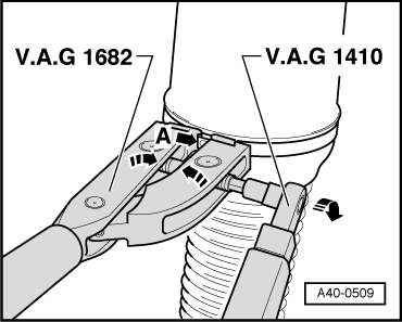
Tightening the Clamping Sleeve on the Air Spring Shock Absorber
- Attach the Clamping Pliers -VAG1682A- as illustrated. When doing that, make sure the jaws on the pliers are centered -arrow A- on the clamping sleeve.
- Tighten the clamp by turning the spindle using a torque wrench (do not tilt the pliers).
- Tightening specification: 8 Nm
- Use torque wrench with 4 to 20 Nm range (for example, Torque Wrench 1410 -VAG1410-).
- Make sure the thread on the spindle -A- is easy to move. Lubricate with MoS2 grease, if necessary.
- If the thread is tight, for example, dirty, the required tensioning force for the hose clamp will not be achieved in spite of correct torque specification settings.
- Tighten the loose threaded connections.