Audi A6 Typ 4G: Spring Mat, Removing and Installing
Removing
 WARNING
- Follow all Safety Precautions when working with pyrotechnic components. Refer to → Chapter "Pyrotechnic Components Safety Precautions".
- Before handling pyrotechnic components (for example, disconnecting the connector), the person handling it must "discharge static electricity". This can be done by touching the door striker, for example.
- Remove the front seat. Refer to → Chapter "Front Seat, Removing and Installing".
- Fasten the front seat on the Engine/Transmission Holder - Seat Repair Fixture -VAS6136-. Refer to → Chapter "Front Seat, Mounting on Fixture for Seat Repair".
- Remove backrest cover and backrest cushion. Refer to → Chapter "Backrest Cover and Padding, Removing and Installing, Standard/Sport Seat".
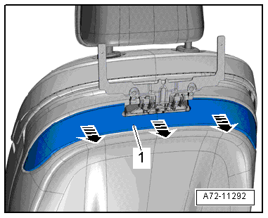
- Remove the springs -A through D- from the backrest frame -1-.
 Note
Note
The springs -A through D- can also stay engaged in the backrest frame -1- and the spring mat -2- can be disengaged directly from the springs.
- Move the spring mat -2- forward.
- Remove the spring mat through the openings in the backrest frame.
Installing
WARNING
- Follow all Safety Precautions when working with pyrotechnic components. Refer to → Chapter "Pyrotechnic Components Safety Precautions".
- Before handling pyrotechnic components (for example, connecting the connector), the person handling it must "discharge static electricity". This can be done by touching the door striker, for example.
Install in reverse order of removal. Note the following:
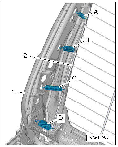
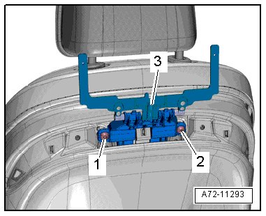
- Label the springs -A through D- as shown in the illustration.
Note
Make sure the connectors are installed correctly and are secure.
WARNING
Ignition must be on when connecting battery. If pyrotechnic components (for example, airbag, belt tensioner) are not repaired correctly, they may deploy unintentionally after connecting battery. There must not be anyone inside the vehicle when connecting the battery.
DANGER!
When working on vehicles with the ignition already switched on or that are ready to drive there is a danger of the engine starting unexpectedly and of being poisoned by gas in enclosed areas. Risk of body parts and/or clothing being clamped or pulled.
Perform the following before switching on the ignition:
- Move the selector lever into P.
- Activate the parking brake
- Turn off the ignition.
- Open the hood
- Connect the charger, such as the Battery Charger -VAS5095A- to the jump start of the 12V vehicle electrical system.
- Turn on the ignition.
- Connect the battery Ground (GND) cable with the ignition turned on. Refer to → Electrical Equipment; Rep. Gr.27; Battery; Battery, Disconnecting and Connecting.
Note
If the Airbag Indicator Lamp -K75- signals a fault after installing, check the Diagnostic Trouble Code (DTC) memory, erase it and check it again. Refer to Vehicle Diagnostic Tester.
Installation notes, for example tightening specifications, replacing components. Refer to → Chapter "Overview - Front Backrest, Spring Mat".
Rear Seat Entertainment Mount/Bracket, Removing and Installing
Special tools and workshop equipment required
- Pop Rivet Nut Pliers -VAS5073A-
- Drill
- Protective eyewear
- 13 mm drill
Removing
Note
The rear seat entertainment mount cannot be removed without being destroyed.
WARNING
Danger of eye injury.
Wear protective eyewear.
- Remove the rear seat entertainment mount guides -1 and 2- with a 13 mm drill.
 Caution
Danger of destroying the backrest cover and cushion.
- The guides are held in the bracket in the backrest frame by the retaining tabs -arrows-.
- Therefore only remove it up the bracket -3- dimension -a-.
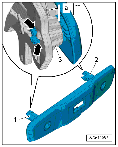
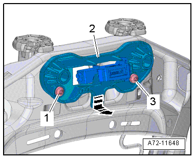
- Remove the rear seat entertainment mount -1- from the bracket on the backrest frame -arrows-.
Note
Remove the drill shavings from the backrest.
- Remove the backrest cover and cushion. Refer to → Chapter "Backrest Cover and Cushion, Removing and Installing".
- Remove the bolts -1 and 3-.
- Unhook the rear seat entertainment bracket -2- on the backrest frame in direction of -arrow-.
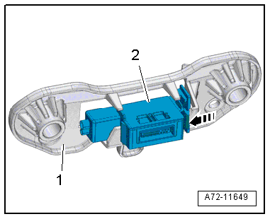
- Release the hooks in direction of -arrow- and unhook the contact -2- on the rear seat entertainment bracket.
- Remove the bracket -1- for the rear seat entertainment.
internally threaded pop rivet, riveting
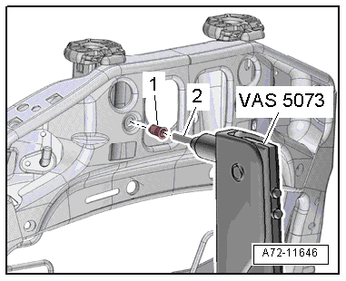
- Insert the M6 threaded pin -item 2- into the Pop Rivet Nut Pliers -VAS5073A- and install the internally threaded pop rivet -1- all the way.
- Insert the pop rivet all the way into the hole in backrest frame and then compress it with the pop rivet pliers.
- Remove the threaded pin with the pop rivet pliers one more time.
Installing
Install in reverse order of removal. Note the following:
Installation notes, for example tightening specifications, replacing components. Refer to → Chapter "Overview - Front Backrest, Rear Seat Entertainment Mount/Bracket".
Rear Seat Entertainment Mount/Bracket, Removing and Installing, Market-Specific
Special tools and workshop equipment required
- Trim Removal Wedge -3409-
Removing
- Remove the Multimedia Display Unit 1 -Y22-/Multimedia Display Unit 2 -Y23-. Refer to → Communication; Rep. Gr.91; Infotainment System; Component Location Overview - Infotainment System.
- Unclip the front cover -1- for the mount upward using the Trim Removal Wedge -3409- in direction of -arrow A- and remove it.
- Release the retainers -2 and 3-, unclip the rear cover -4- for the mount using the Trim Removal Wedge -3409- in direction of -arrow B- and remove it.
- Unclip the trim -1- using the Trim Removal Wedge -3409- in direction of -arrows- and remove.
- Remove the bolts -1 and 2-.
- Detach mount -3- on the bracket and remove.
Installing
Install in reverse order of removal. Note the following:
Installation notes, for example tightening specifications, replacing components. Refer to → Chapter "Overview - Front Backrest, Rear Seat Entertainment Mount/Bracket".
Front Backrest Fan, Removing and Installing
Special tools and workshop equipment required
- Trim Removal Wedge -3409-
Removing
Standard Seat/Sport Seat/Super Sport Seat
- Remove the backrest cover. Refer to → Chapter "Backrest Cover, Removing and Installing, Standard Seat/Sport Seat/Super Sport Seat".
Upper Fan
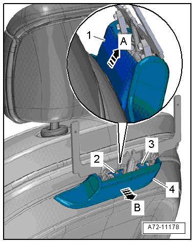
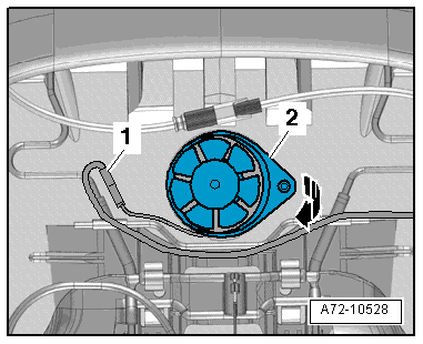
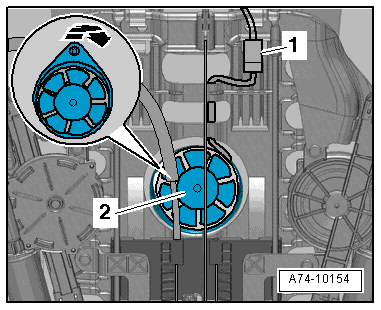
- Free up the connector -1- and disconnect.
- Carefully pry the backrest fan -2- out of the backrest cushion using the Trim Removal Wedge -3409--arrow-.
Lower Fan
- Adjust the lumbar support to the highest curve while moving the slider -1- all the way down -arrow A-.
Note
Ignore item -2-.
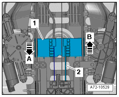
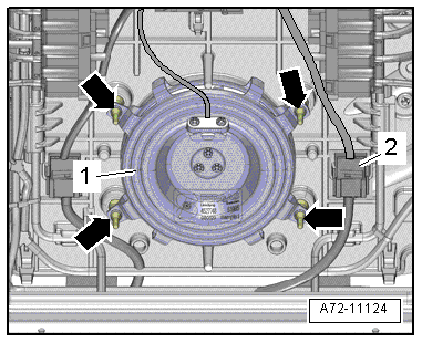
- Disconnect and free up the connector -1-.
- Carefully pry the backrest fan -2- out of the backrest cushion using the Trim Removal Wedge -3409--arrow-.
Multi-Contour Seat
- Remove the backrest cover. Refer to → Chapter "Backrest Cover, Removing and Installing, Multi-contour Seat".
- Disconnect the connector -2- and free it up.
- Spray the rubber protrusions -arrows- of the elastic blower fan mount -1- with silicon-free lubricating spray.
- Detach blower fan from the rubber protrusions and remove it.
Installing
Install in reverse order of removal. Note the following:
Installation notes, for example tightening specifications, replacing components. Refer to → Chapter "Component Location Overview - Electric and Electronic Components, Seat Ventilation Fan".
Headrest, Removing and Installing
Note
The headrests can be removed with the front seats installed.
Removing
- Move the front seat forward into the lowest position and tilt the backrest approximately 45º.
Vehicles with Basic Seats
Note
The release button is located on the outer left of the driver seat and inner left of the passenger seat.
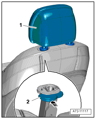
- Search for release button pressure point -2- under the seat cover.
- The release button is approximately 35 mm below the upper edge of the backrest.
- Press release button -arrow- and simultaneously pull out headrest -1-.
Vehicles with Comfort Seats
Note
The release button is located on the left and right headrest guide.
- Search for release button pressure point -2- under the seat cover.
- The release button is approximately 35 mm below the upper edge of the backrest.
- Pull on both sides of the headrest -1- and remove it from the headrest guide.
- Press the release button -arrow- and remove the headrest at the same time.
Installing
Install in reverse order of removal. Note the following:
Installation notes, for example tightening specifications, replacing components. Refer to → Chapter "Overview - Headrest".
Headrest Guide, Removing and Installing
Removing
WARNING
- Follow all Safety Precautions when working with pyrotechnic components. Refer to → Chapter "Pyrotechnic Components Safety Precautions".
- Before handling pyrotechnic components (for example, disconnecting the connector), the person handling it must "discharge static electricity". This can be done by touching the door striker, for example.
- Remove the front seat. Refer to → Chapter "Front Seat, Removing and Installing".
- Fasten the front seat on the Engine/Transmission Holder - Seat Repair Fixture -VAS6136-. Refer to → Chapter "Front Seat, Mounting on Fixture for Seat Repair".
- Remove the backrest cover with the backrest cushion. Refer to → Chapter "Backrest Cover and Cushion, Removing and Installing".
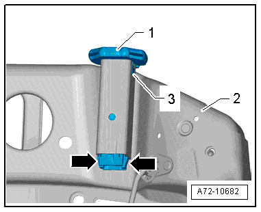
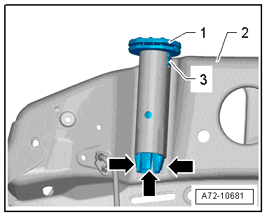
Right Headrest Guide
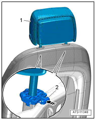
- Press retaining tabs in -arrows- and simultaneously pull the headrest guide -1- out of the backrest frame -2-.
Left Headrest Guide
- Press in retaining tab -arrows- and simultaneously pull headrest guide -1- out of the backrest frame -2-.
Installing
Note
- The headrest guide can only be inserted in one position.
- The guide tab -3- on the headrest guide must engage in cut-out of mount on the backrest frame.
- Make sure the retaining tab(s) engage(s) correctly in backrest frame.
Installation is performed in reverse order of removal, while noting the following:
WARNING
- Follow all Safety Precautions when working with pyrotechnic components. Refer to → Chapter "Pyrotechnic Components Safety Precautions".
- Before handling pyrotechnic components (for example, connecting the connector), the person handling it must "discharge static electricity". This can be done by touching the door striker, for example.
- Observe all measures when installing the front seat. Refer to → Chapter "Front Seat, Removing and Installing".
Installation notes, for example tightening specifications, replacing components. Refer to → Chapter "Overview - Headrest".