Audi A6 Typ 4G: Stabilizer Bar
Overview - Stabilizer Bar
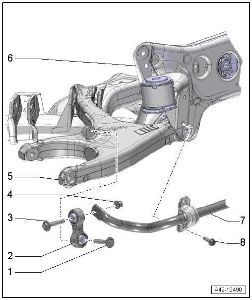
1 - Bolt
- 40 Nm +90º turn
- Always replace if removed
- Must be tightened in the curb weight position. Refer to → Chapter "Wheel Bearing in Curb Weight, Lifting Vehicles with Coil Spring".
2 - Coupling rod
- Removing and installing. Refer to → Chapter "Stabilizer Bar, Removing and Installing".
3 - Bolt
- 40 Nm +90º turn
- Always replace if removed
- Must be tightened in the curb weight position. Refer to → Chapter "Wheel Bearing in Curb Weight, Lifting Vehicles with Coil Spring".
4 - Nut
- Always replace if removed
5 - Lower Transverse Link
6 - Subframe
7 - Stabilizer Bar
- Removing and installing. Refer to → Chapter "Stabilizer Bar, Removing and Installing".
- The rubber bushing and clamp must not be separated from the stabilizer bar.
8 - Bolt
- 25 Nm +90º turn
- Always replace if removed
- Tighten evenly
Stabilizer Bar, Removing and Installing
Special tools and workshop equipment required
- Torque Wrench 1331 5-50Nm -VAG1331-
- Engine and Gearbox Jack -VAS6931-
Removing
 Caution
Do not damage the paint on the stabilizer bar when removing and installing.
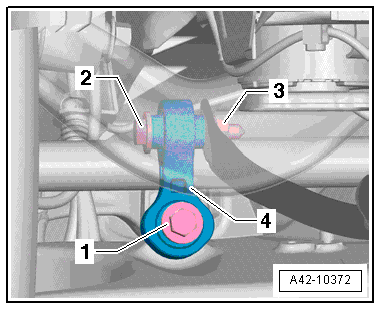
- Remove the bolt -1-.
 Note
Note
- The threaded connection between the coupling rod and the lower transverse link is under tension.
- Press the lower transverse link gently downward when removing the bolt -1-.
- Remove the nut -3-, the bolt -2- and the coupling rod -4-.
- Remove the rear section from the exhaust system. Refer to → Rep. Gr.26; Exhaust Pipes/Mufflers; Overview - Muffler.
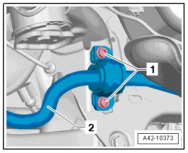
- Remove the left and right bolts -1-. Then remove the stabilizer bar -2- to the left.
Note
The stabilizer bar -2- is removed and installed completely with the rubber bushings and clamps. Do not remove the clamps and rubber bushings.
Installing
Install in reverse order of removal. Note the following:
Note
- Bonded rubber bushings have a limited range of motion. Only tighten suspension bolts when vehicle is in curb weight or control position.
- For lifting the wheel bearing into curb weight position, vehicles with steel suspension. Refer to → Chapter "Wheel Bearing in Curb Weight, Lifting Vehicles with Coil Spring".
- For vehicles with air spring suspension, lift wheel suspension in control position. Refer to → Chapter "Wheel Bearing in Control Position, Lifting Vehicles with Air Suspension".
- Install the stabilizer bar from the left side.
- Install the left and right bolts -1- so they are still loose and then tighten them evenly.
- Install the coupling rod -4- and bolt -2-.
- Tighten the left and right nuts -3-.
- Tighten the left and right bolts -1-.
- Install the rear section from the exhaust system. Refer to → Rep. Gr.26; Exhaust Pipes/Mufflers; Overview - Muffler.
