Audi A6 Typ 4G: Overview - Transverse Link
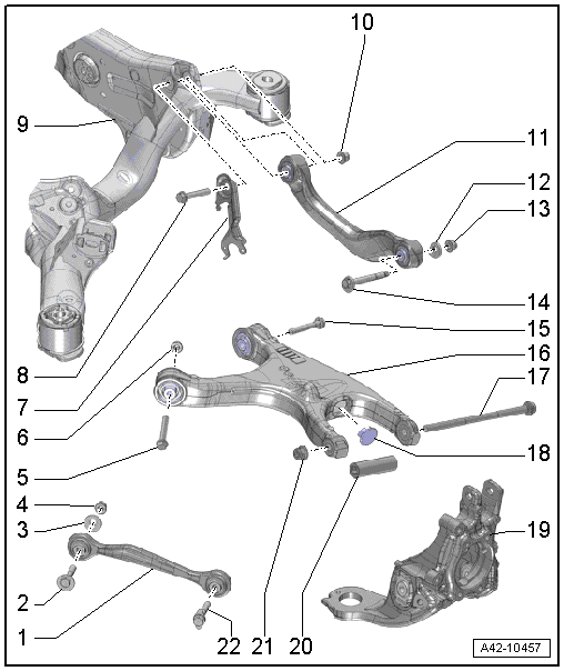
1 - Tie Rod
- Removing and installing. Refer to → Chapter "Tie Rod, Removing and Installing".
- There are different versions and installed positions. Refer to → Fig. "Tie Rod on A Vehicle with Steel Suspension" and → Fig. "Tie Rod on A Vehicle with Air Suspension". For the correct allocation. Refer to the Parts Catalog.
2 - Eccentric Bolt
- Always replace if removed
- Tighten either in the curb weight position (refer to → Chapter "Wheel Bearing in Curb Weight, Lifting Vehicles with Coil Spring") or in the control position (refer to → Chapter "Wheel Bearing in Control Position, Lifting Vehicles with Air Suspension").
3 - Eccentric Washer
4 - Nut
- 95 Nm
- Always replace if removed
5 - Bolt
- 70 Nm +180º turn
- Always replace if removed
- Tighten either in the curb weight position (refer to → Chapter "Wheel Bearing in Curb Weight, Lifting Vehicles with Coil Spring") or in the control position (refer to → Chapter "Wheel Bearing in Control Position, Lifting Vehicles with Air Suspension").
6 - Nut
- Always replace if removed
7 - Bracket
- For the Left Rear Level Control System Sensor -G76- / Right Rear Level Control System Sensor -G77-
8 - Bolt
- 70 Nm +180º turn
- Always replace if removed
- Tighten either in the curb weight position (refer to → Chapter "Wheel Bearing in Curb Weight, Lifting Vehicles with Coil Spring") or in the control position (refer to → Chapter "Wheel Bearing in Control Position, Lifting Vehicles with Air Suspension").
9 - Subframe
10 - Nut
- Always replace if removed
11 - Upper Transverse Link
- Removing and installing. Refer to → Chapter "Upper Transverse Link, Removing and Installing".
12 - Shim
13 - Nut
- 95 Nm
- Always replace if removed
- Tighten either in the curb weight position (refer to → Chapter "Wheel Bearing in Curb Weight, Lifting Vehicles with Coil Spring") or in the control position (refer to → Chapter "Wheel Bearing in Control Position, Lifting Vehicles with Air Suspension").
14 - Adjusting Bolt
15 - Bolt
- 70 Nm +180º turn
- Always replace if removed
- Tighten either in the curb weight position (refer to → Chapter "Wheel Bearing in Curb Weight, Lifting Vehicles with Coil Spring") or in the control position (refer to → Chapter "Wheel Bearing in Control Position, Lifting Vehicles with Air Suspension").
16 - Lower Transverse Link
- Removing and installing. Refer to → Chapter "Lower Transverse Link, Removing and Installing".
17 - Bolt
- 120 Nm +360º turn
- Always replace if removed
- Tighten either in the curb weight position (refer to → Chapter "Wheel Bearing in Curb Weight, Lifting Vehicles with Coil Spring") or in the control position (refer to → Chapter "Wheel Bearing in Control Position, Lifting Vehicles with Air Suspension").
 Note
Note
Axle alignment is necessary if the bolt is loosened.
18 - Cap
19 - Wheel Bearing Housing
20 - Spacer Tube
- Always replace if removed
21 - Nut
- Always replace if removed
 Caution
Do not tighten the threaded connection using the nut.
Note
Axle alignment is necessary if the nut is loosened.
22 - Bolt
- 90 Nm +90º turn
- Always replace if removed
- Tighten either in the curb weight position (refer to → Chapter "Wheel Bearing in Curb Weight, Lifting Vehicles with Coil Spring") or in the control position (refer to → Chapter "Wheel Bearing in Control Position, Lifting Vehicles with Air Suspension").
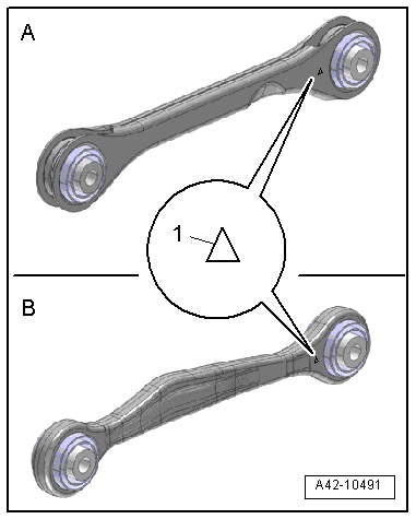
Tie Rod on A Vehicle with Steel Suspension
A - Steel tie rod
B - Aluminum cast tie rod
1 - Installed position: The marking must be on the outside and the tip of the triangle points up.
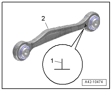
Tie Rod on A Vehicle with Air Suspension
1 - Installed position: The marking must be on the outside and the horizontal line points up.
2 - Aluminum cast tie rod