Audi A6 Typ 4G: Stabilizer Bar, Removing and Installing
Special tools and workshop equipment required
- Torque Wrench 1332 40-200Nm -VAG1332-
- For a vehicle with air suspension Vehicle Diagnostic Tester
Removing
- Place the vehicle on a hoist. Refer to → Chapter "Raising and Lowering with Open and Closed Air Suspension System".
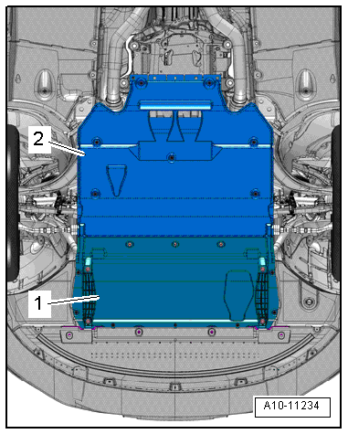
- Remove the noise insulation -1-. Refer to → Body Exterior; Rep. Gr.66; Noise Insulation; Noise Insulation, Removing and Installing.
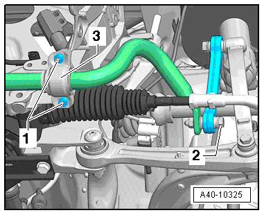
- Disconnect left and right connectors -2-.
- Remove the left and right threaded connector -1- and remove the clamps -3-.
- Remove the stabilizer bar.
Installing
Install in reverse order of removal. Note the following:
 Note
Note
- Bonded rubber bushings have a limited range of motion. Only tighten suspension bolts when vehicle is in curb weight or control position.
- Lift the wheel bearing into the curb weight or control position. Refer to → Chapter "Wheel Bearing in Control Position, Lifting Vehicles with Air Suspension" or → Chapter "Wheel Bearing in Curb Weight, Lifting Vehicles with Coil Spring".
- There must be no grease on the stabilizer bar and rubber bushing.
- Install the rubber bushing opening in the direction of the subframe contact surface.
- Before installing the clamp -3- again (if equipped) install any loose stud bolts -1- all the way.
- Install the threaded connector -1- but do not tighten it.
- Install the left and right threaded connections -2- but do not tighten them.
- Lift wheel bearing in control position. Refer to → Chapter "Wheel Bearing in Control Position, Lifting Vehicles with Air Suspension" or → Chapter "Wheel Bearing in Curb Weight, Lifting Vehicles with Coil Spring".
- Tighten connections -1 and 2-.
Note
- Install the threaded connector -1- alternating from side to side evenly.
- The opening on the rubber bushing must be facing up when installing the subframe.
- There must not be any grease on the stabilizer bar and rubber bushing when installing them.
Coupling Rod, Removing and Installing
Special tools and workshop equipment required
- Torque Wrench 1332 40-200Nm -VAG1332-
- For a vehicle with air suspension Vehicle Diagnostic Tester
Removing
- Place the vehicle on a hoist. Refer to → Chapter "Raising and Lowering with Open and Closed Air Suspension System".
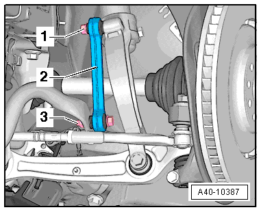
- Disconnect the bolting -1 and 3-.
- Remove the coupling rod -2-.
Installing
Install in reverse order of removal. Note the following:
Note
- Note the installation position of the coupling rod.
- Bonded rubber bushings have a limited range of motion. Only tighten suspension bolts when vehicle is in curb weight or control position.
- Lift wheel bearing in control position. Refer to → Chapter "Wheel Bearing in Control Position, Lifting Vehicles with Air Suspension" or → Chapter "Wheel Bearing in Curb Weight, Lifting Vehicles with Coil Spring".
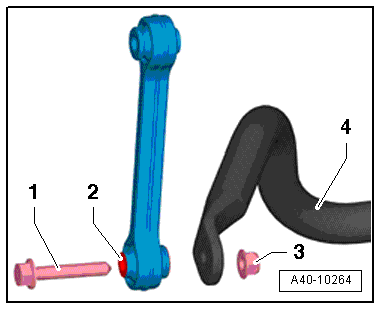
- The bolt -1- for connecting the coupling rod to the stabilizer bar -4- must be attached to the "small" surface -2- of the coupling rod collar and secured with the nut -3-.
- Install the threaded connections -1 and 3- but do not tighten them.
- Lift wheel bearing in control position. Refer to → Chapter "Wheel Bearing in Control Position, Lifting Vehicles with Air Suspension" or → Chapter "Wheel Bearing in Curb Weight, Lifting Vehicles with Coil Spring".
- Tighten the threaded connections -1 and 3-.
