Audi A6 Typ 4G: Suspension Strut, Filling
 Note
Note
The procedure refers to the air spring damper.
Special tools and workshop equipment required
- Air Spring Strut Adapter -T10157-
- Air Suspension Strut Charger -VAS6231-
- Steel gas bottle filled with argon or corgon
Note
Air spring shock absorbers are supplied as replacement parts with a minimum pressure. By sitting in storage for extended periods this pressure can diminish (just like a tire). This minimum pressure must be checked and if necessary restored by "recharging" before air spring shock absorber is removed from the packaging. If air spring shock absorber is removed from the packaging without this checking/recharging, this may cause indentations or kinks to form in the dust boot before it reaches its normal shape. These folds can cause damage and premature failure of the air spring damper.
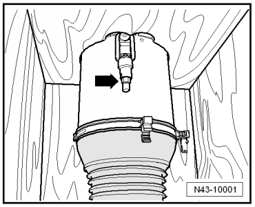
- Remove the cover from the packaging.
- Remove union bolt -arrow- from the residual pressure retaining valve.
- Close the valve of the steel gas bottle.
- Become familiar with the relevant rules for the prevention of accidents for pressurized containers and technical gases.
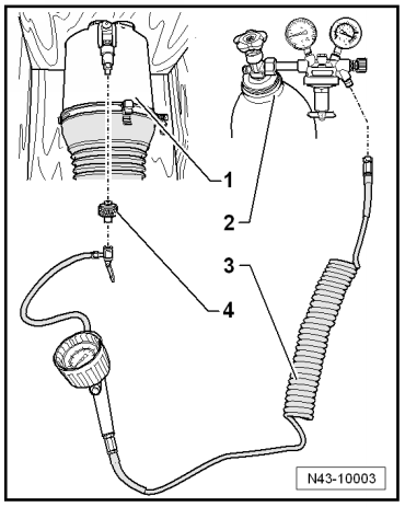
- Connect the Air Suspension Strut Charger -VAS6231- and Air Spring Strut Adapter -T10157- as shown.
1 - Air spring shock absorber in packaging
2 - Steel gas bottle for argon, corgon with gauges
3 - Air Suspension Strut Charger -VAS6231-
4 - Air Spring Strut Adapter -T10157-
Note
Refilling the suspension strut (air suspension) may only be performed with the gases from the top to prevent any "uncleaned" air from getting into the air suspension system.
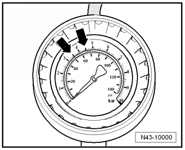
- Set flow rate limiter gauge to 2.0 liters/min -arrow-.
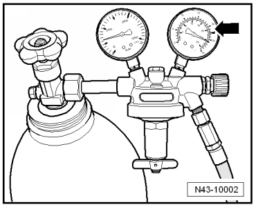
- Now fill gas into air spring shock absorber approximately up to 5 bar (72.5 psi) using several individual pressure bursts.
- Disconnect the Air Suspension Strut Charger -VAS6231- from the Air Spring Strut Adapter -T10157-. When doing this, gas will escape at a pressure greater than 3.5 bar (50.7 psi).
Minimum pressure is now reestablished. You can remove air spring damper from packaging.
- After installation, first drive the vehicle at high ride height and then at normal ride height. Repeat this sequence once more.
By moving the vehicle lever heights twice, the majority of the gas is exchanged with filtered air from the air supply motor.
- Install the air spring shock absorber.
Shock Absorber Fork, Removing and Installing
Special tools and workshop equipment required
- Spreader Tool -3424-
- Torque Wrench 1331 5-50Nm -VAG1331-
- Torque Wrench 1332 40-200Nm -VAG1332-
- Tensioning Strap -T10038-
- Puller - Ball Joint -T40010A-
Removing
- Remove the plenum chamber cover. Refer to → Body Exterior; Rep. Gr.50; Bulkhead; Plenum Chamber Cover, Removing and Installing.
- Remove the wheel. Refer to → Chapter "Wheels and Tires".
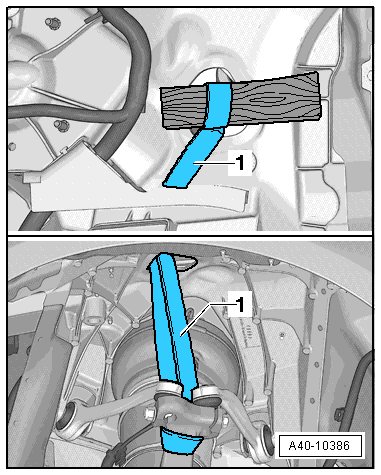
- Secure the wheel bearing housing using a Tensioning Strap -T10038--1-, as illustrated.
Note
To prevent the joints on the upper control arm from being damaged, support the wheel bearing housing.
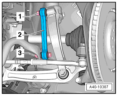
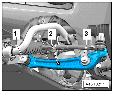
- Disconnect the bolting -1 and 3-.
- Remove the coupling rod -2-.
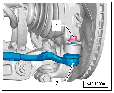
- Remove the nut -1- from the tie rod end joint pin -2- until it is flush with the joint pin threads. Counterhold when loosening.
Note
To protect thread, screw nut on pin a few turns.
- Remove the tie rod end from the wheel bearing housing using the Puller - Ball Joint -T40010A-. Remove the nut.
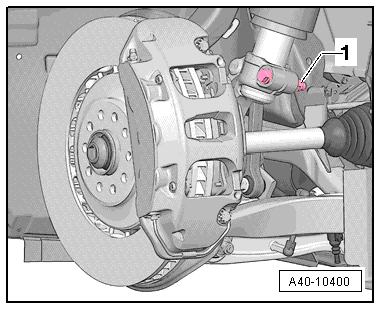
- Disconnect the bolting -2 and 3-.
- Disconnect the bolting -1- and guide the control arm out and tilt it forward.
Note
To remove the bolt -1-, turn the steering gear all the way to the left or right depending on the side of the vehicle.
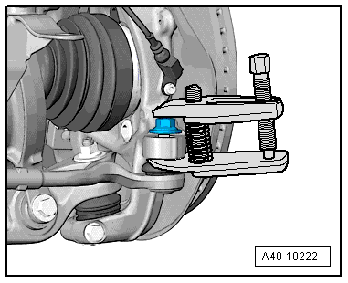
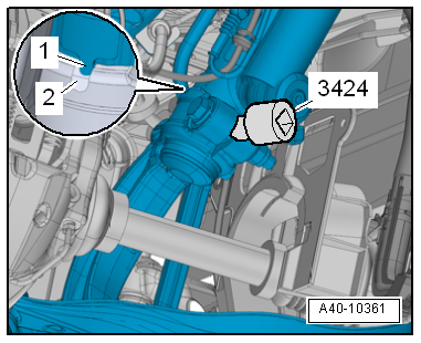
- Disconnect the threaded connection -1-.
- Insert the Spreader Tool -3424- into the slot in the shock absorber fork.
- Turn the ratchet 90º and remove it from the Spreader Tool -3424--1-.
- Pull the shock absorber fork downward from the shock absorber tube and remove it.
Installing
Install in reverse order of removal. Note the following:
Note
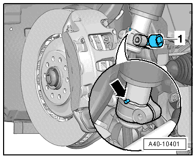
- Version 1: When connecting, make sure the T-pins -arrow- engage in the shock absorber fork groove.
- Version 2: When connecting, make sure the pins -1- engage in the groove -2- on the shock absorber fork.
- Bonded rubber bushings have a limited range of motion. Only tighten suspension bolts when vehicle is in curb weight or control position.
- Lift the wheel bearing into the control position or into the curb weight position. Refer to → Chapter "Wheel Bearing in Control Position, Lifting Vehicles with Air Suspension" or → Chapter "Wheel Bearing in Curb Weight, Lifting Vehicles with Coil Spring".
- On vehicles with automatic head lamp range control, perform headlamp basic setting. Refer to → Electrical Equipment; Rep. Gr.94; Headlamp; Headlamp, Adjusting.
- If the Level Control Sensor was removed and installed or if the linkage was loosened, the control position must be programmed again. Refer to → Chapter "Control Position, Programming".
- If the control position was reprogrammed on vehicles with lane assist, the Camera Control Module -J852- must be calibrated again. Refer to → Chapter "Driver Assistance Systems Front Camera, Calibrating".
- Install the wheel. Refer to → Chapter "Wheels and Tires".
- To determine if an axle alignment is required, see Table. Refer to → Chapter "Evaluating Need for Axle Alignment".
Tower Brace, Removing and Installing
Special tools and workshop equipment required
- Torque Wrench 1783 - 2-10Nm -VAG1783-
- Torque Wrench 1331 5-50Nm -VAG1331-
Removing
- Remove the plenum chamber cover. Refer to → Body Exterior; Rep. Gr.50; Bulkhead; Plenum Chamber Cover, Removing and Installing.
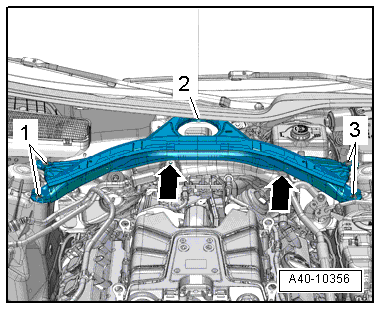
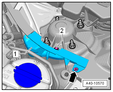
- Remove the left and right expanding rivets -arrows- and the nuts -2- and unclip the cover -1-.
- Remove the bolts -1 through 3- and -arrows- and remove the tower brace.
Installing
Install in reverse order of removal.