Audi A6 Typ 4G (2011–2018) Workshop Manual / Chassis / Suspension, Wheels, Steering / Front Suspension / Overview - Lower Control Arm and Ball Joint
Audi A6 Typ 4G: Overview - Lower Control Arm and Ball Joint
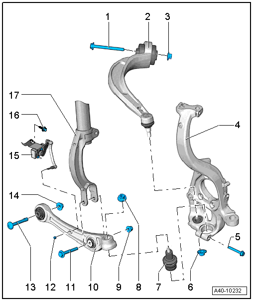
1 - Bolt
- Always replace if removed
2 - Guide Link
- Removing and installing. Refer to → Chapter "Guide Link, Removing and Installing".
- For removing and installing the guide link bonded rubber bushing. Refer to → Chapter "Guide Link Bonded Rubber Bushing, Removing and Installing".
3 - Nut
- 70 Nm +180º turn
- Always replace if removed
- Must be tightened in the control position. Refer to → Chapter "Wheel Bearing in Control Position, Lifting Vehicles with Air Suspension" or → Chapter "Wheel Bearing in Curb Weight, Lifting Vehicles with Coil Spring".
4 - Wheel Bearing Housing
5 - Bolt
- 40 Nm
- Always replace if removed
6 - Nut
- 140 Nm
- Always replace if removed
- After loosening threaded connection of guide control arm to wheel bearing housing, adhesive residue must be removed on thread of linkage stub.
7 - Ball Joint
- Removing and installing. Refer to → Chapter "Ball Joint, Removing and Installing".
- There are different versions. For allocation. Refer to the Parts Catalog.
 Note
Note
- Note installation position.
- Install the ball joint into the wheel bearing housing as far as the contact surface.
8 - Nut
- M12: 120 Nm
- M14: 140 Nm
- There are different versions. For allocation. Refer to the Parts Catalog.
- Always replace if removed
- After loosening threaded connection on the ball joint to the wheel bearing housing, adhesive residue must be removed on thread of linkage stub.
9 - Nut
- 90 Nm +90º turn
- Always replace if removed
- Must be tightened in the control position. Refer to → Chapter "Wheel Bearing in Control Position, Lifting Vehicles with Air Suspension" or → Chapter "Wheel Bearing in Curb Weight, Lifting Vehicles with Coil Spring".
10 - Control Arm
- Removing and installing. Refer to → Chapter "Control Arm, Removing and Installing".
- There are different versions. For allocation. Refer to the Parts Catalog.
- For removing and installing the control arm bonded rubber bushing on the wheel bearing housing side. Refer to → Chapter "Control Arm Ball Bearing, Replacing, Wheel Bearing Housing Side".
- For removing and Installing the control arm bonded rubber bushing on the subframe side. Refer to → Chapter "Control Arm Ball Bearing, Replacing, Subframe Side".
11 - Bolt
- Always replace if removed
12 - Nut
- 9 Nm
13 - Bolt
- Always replace if removed
14 - Nut
- 70 Nm +180º turn
- Always replace if removed
- Must be tightened in the control position. Refer to → Chapter "Wheel Bearing in Control Position, Lifting Vehicles with Air Suspension" or → Chapter "Wheel Bearing in Curb Weight, Lifting Vehicles with Coil Spring".
15 - Left Front Level Control System Sensor -G78- or Right Front Level Control Sensor -G289-
- Only remove and install or replace completely. Refer to → Chapter "Left/Right Front Level Control System Sensor -G78-/-G289-, Removing and Installing".
- The sensor lever must point toward the back
- Perform the headlamp adjustment after loosening. Refer to → Electrical Equipment; Rep. Gr.94; Headlamp; Headlamp, Adjusting.
- If the Level Control Sensor was removed and installed or if the linkage was loosened, the control position must be programmed again by starting the correct program on the Vehicle Diagnostic Tester in Guided Functions.
- If the control position was reprogrammed on vehicles with lane assist, the Camera Control Module -J852- must be calibrated again. Refer to → Chapter "Driver Assistance Systems Front Camera, Calibrating".
16 - Bolt
- 9 Nm
17 - Shock Absorber Fork
