Audi A6 Typ 4G: Wheel Electronics, New Design
Assembly Sequence
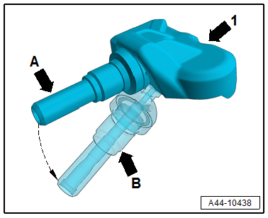
- Fold the valve -1- downward -arrow A toward B-.
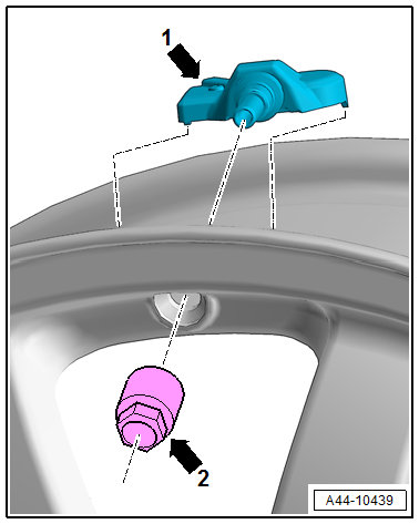
- Slide the valve with the wheel electronics attached through the valve opening in the rim.
- Rotate the union nut -2- three turns on the valve -1-.
- Tighten the union nut -2- until the bar breaks with an audible snap.
 Note
Note
Press the wheel electronics -1- firmly on the rim well at the same time so that it rests securely on the rim well.
- Tighten the union nut to 4 Nm.
Wheel Rims, Preparing
Preparing the Wheel Rims
 WARNING
- Do not repair damaged rims by heating, welding or adding or removing material.
- Do not repair damaged or deformed rims or rims with cracked or deformed bolt holes.
- Only prepare wheels with tested and specified original paint materials.
- No warranty claims can be made against the manufacturer after preparing rims.
Do not repair rims that have cracks forming on the edges. Replace them immediately.
Cutting work, application of heat and welding applications of any kind are not permitted.
Reshaping material is not permitted.
The true running and axial run-out deviations before preparation must not exceed the manufacturing tolerance of 0.8 mm.
Only cast light alloy wheels may be primed. These wheels have the material identification AIsi xx on the inside.
Forged wheels may only be painted.
Preparation is limited to the painted surfaces.
Wheels that have been worn smooth that only have a clear coat may not be repaired.
Only surface damage on the visible side of the wheel may be prepared.
Damage must not be more than 1 mm deep.
Up to 50 mm of the rim flange can be repaired and filled (up to 1 mm deep).
