Audi A6 Typ 4G: Windshield Antenna Suppression Filter -C18-, Removing and Installing
Windshield Antenna Suppression Filter -C18-, Removing and Installing, Sedan
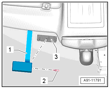
The Windshield Antenna Suppression Filter -C18- is located behind the right D-pillar trim panel.
Removing
- Turn off the ignition and all electrical equipment and remove the ignition key.
- Remove the D-pillar trim panel. Refer to → Body Interior; Rep. Gr.70; Vehicle Interior Trim Panels; D-Pillar Trim Panel, Removing and Installing.
- Remove the nuts -1- and -3- from the Windshield Antenna Suppression Filter -C18--4-.
- Disconnect the wires on the Windshield Antenna Suppression Filter -C18--1-.
- Remove the nut -2- and then remove the Windshield Antenna Suppression Filter -C18--1- from the D-pillar.
Installing
- Installation is identical in reverse order of removal.
Windshield Antenna Suppression Filter -C18-, Removing and Installing, Avant
The Windshield Antenna Suppression Filter -C18- is located behind the right rear lid trim panel.
Removing
- Turn off the ignition and all electrical equipment and remove the ignition key.
- Remove the lower rear lid trim panel. Refer to → Body Interior; Rep. Gr.70; Luggage Compartment Trim Panel; Rear Lid Lower Trim Panel, Removing and Installing.
- Remove the nuts -2- and -4- on the Windshield Antenna Suppression Filter -C18--1-.
- Disconnect the wires on the Windshield Antenna Suppression Filter -C18--1-.
- Remove the nut -3- and then remove the Windshield Antenna Suppression Filter -C18--1- from the rear lid.
Installing
- Installation is identical in reverse order of removal.
Traffic Data Antenna, Removing and Installing
The Traffic Data Antenna -R173- is located at the top of the windshield on the left side.
Removing
- Turn off the ignition and all electrical equipment and remove the ignition key.
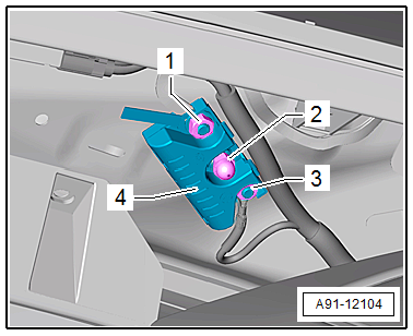
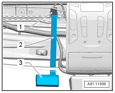
The connectors -1- for the Traffic Data Antenna -R173--3- are located on the roof crossmember, behind the left sun visor. The flat band cable -2- is routed on the roof crossmember. The headliner must be removed in order to remove the flat band cable.
- Remove the headliner. Refer to → Body Interior; Rep. Gr.70; Roof Trim Panels; Headliner, Removing and Installing.
- Disconnect the connector -1-.
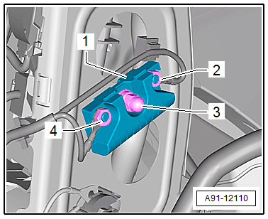
Traffic Data Antenna -R173- removal:
A safety piece -2- secures the Traffic Data Antenna -R173--1- to its bracket -3-. The bracket is glued to the windshield -3-.
- Remove the safety piece -2- with a small screwdriver.
- Remove the Traffic Data Antenna -R173--1- from the bracket -3-.
Installing
- Installation is identical in reverse order of removal.
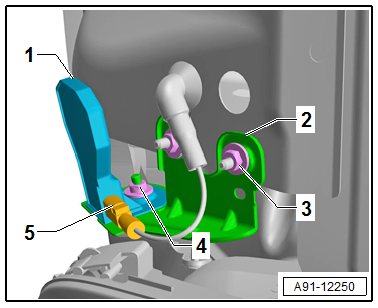
Close Range Communication Antenna -R269-, Removing and Installing
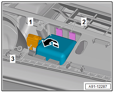
The Close Range Communication Antenna -R269- is located in the center of the instrument panel.
- Turn off the ignition and all electrical equipment and remove the ignition key.
Removing
- Remove the center speaker trim in the instrument panel. Refer to → Body Interior; Rep. Gr.70; Instrument Panel; Overview - Instrument Panel.
- Release the catches -2- for the Close Range Communication Antenna -R269--1-.
- Tilt the Close Range Communication Antenna -R269--1- in the direction of the -arrow- out of the holder in the instrument panel.
- Release and disconnect the connector -3- from the Close Range Communication Antenna -R269--1-.
- Remove the Close Range Communication Antenna -R269-.
Installing
- Installation is identical in reverse order of removal.
Roof Antenna, Removing and Installing
The Roof Antenna -R216- has a maximum of four connections.
The antenna wires are connected directly to the base of the Roof Antenna -R216-.
The rear headliner must be removed/lowered in order to remove the Roof Antenna -R216-.
Removing
- Turn off the ignition and all electrical equipment and remove the ignition key.
Sedan
- Remove the complete headliner. Refer to → Body Interior; Rep. Gr.70; Roof Trim Panels; Headliner, Removing and Installing and set it on the front of the instrument panel.
Avant
- Lower the back of the headliner. Refer to → Body Interior; Rep. Gr.70; Roof Trim Panels; Headliner, Removing and Installing.
All Vehicles
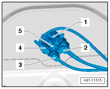
- Unlock and disconnect the connectors -2-, -3- and -4- from the antenna wires.
- Remove the bolt -5- and the retaining spring.
- Remove the Roof Antenna -R216- upward from the roof.
Installing
The Roof Antenna -R216- is supplied pre-assembled. The Roof Antenna -R216-, spring and screw are installed.
- Place the Roof Antenna -R216- on the roof and press down on it until it engages.
- Tighten the pre-mounted bolt to the given tightening specification.
- Installation is identical in reverse order of removal.
Bumper Antennas, Removing and Installing
Depending on vehicle equipment and the market versions, the following antennas are located under the rear bumper cover.
Under the rear bumper cover on the left side:
- Telephone Antenna -R65-, only on 9ZC and ER1/ER2
- LTE Antenna 1 -R297-, only on 9ZK and ER1/ER2/ER5 (from 11/08/2015)/ER6 (from MY 2017)
- LTE Antenna 2 -R306-, only on 9ZC/9ZK and ER3
Under the rear bumper cover on the right side:
- LTE Antenna 1 -R297-, only on 9ZC and ER1/ER2
- LTE Antenna 1 -R297-, only on 9ZC/9ZK and ER3
Removing
- Turn off the ignition and all electrical equipment and remove the ignition key.
- Remove the rear bumper cover. Refer to → Body Exterior; Rep. Gr.63; Rear Bumper; Bumper Cover, Removing and Installing.
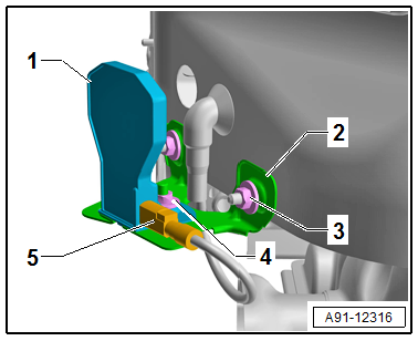
Bumper antenna under the rear bumper cover on the right side.
- Release and disconnect the connector -5- for the bumper antenna -1-
- Remove the nut -4- for the bumper antenna -1-.
- Remove the bumper antenna -1- from the bracket -2-.
- Remove the nuts -3- for the bracket -2-
- Remove the bracket -2- from the body.
Bumper antenna under the rear bumper cover on the left side.
- Release and disconnect the connector -5- for the bumper antenna -1-
- Remove the nut -4- for the bumper antenna -1-.
- Remove the bumper antenna -1- from the bracket -2-.
- Remove the nuts -3- for the bracket -2-
- Remove the bracket -2- from the body.
Installing
- Installation is identical in reverse order of removal.
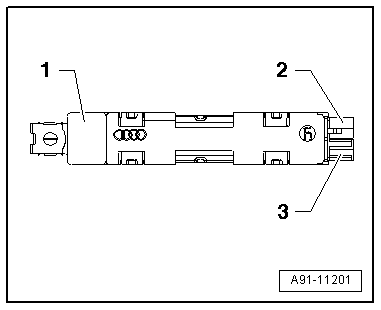
Connector Assignments
Antenna Amplifier 2 -R111- Sedan/Avant
1 - Radio Antenna 2 -R93- (AM/FM1)/Central Locking and Anti-Theft Alarm System Antenna -R47- (CLS)
2 - AM/FM1 connection to the Radio -R-/Information Electronics Control Module 1 -J794-
3 - CLS connection to Comfort System Central Control Module -J393-
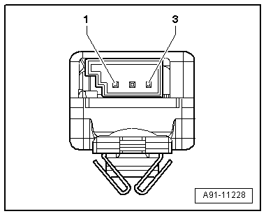
Window Antenna Connector
1 - AM
2 - FM1/Diagnosis
3 - CLS
Antenna Amplifier -R24-, Sedan
1 - Antenna -R11- (FM2)/TV Antenna 2 -R56- (TV2)
2 - FM2 connection to the Radio -R-/Information Electronics Control Module 1 -J794-
3 - TV2 connection to the TV Tuner -R78-
Window Antenna Connector
1 - Not Assigned
2 - FM2/TV2/diagnosis
3 - Not Assigned
Antenna Amplifier -R24-, Avant
1 - Antenna -R11- (FM2) /TV Antenna 1 -R55- (TV1)
2 - FM2 connection to the Radio -R-/Information Electronics Control Module 1 -J794-
3 - TV1 connection to the TV Tuner -R78-
Window Antenna Connector
1 - Not Assigned
2 - FM2/TV1/diagnosis
3 - Not Assigned
Antenna Amplifier 3 -R112-, Sedan
1 - Digital Radio Antenna -R183- (DAB)/TV Antenna 1 - R55- (TV1)
2 - TV1 connection to the TV Tuner -R78-
3 - DAB connection to the Radio -R-/Information Electronics Control Module 1 -J794-
Window Antenna Connector
1 - DAB
2 - TV1/diagnosis
3 - Not Assigned
Antenna Amplifier 3 -R112-, Avant
1 - Digital Radio Antenna -R183- (DAB)/TV Antenna 3 -R57- (TV3)
2 - TV3 connection to the TV Tuner -R78-
3 - DAB connection to the Radio -R-/Information Electronics Control Module 1 -J794-
Window Antenna Connector
1 - DAB
2 - TV3/diagnosis
3 - Not Assigned
Antenna Amplifier 4 -R113-, Sedan
1 - TV Antenna 3 -R57-, TV3
2 - TV3 connection to the TV Tuner -R78-
3 - Not Assigned
Window Antenna Connector
1 - Not Assigned
2 - TV3/diagnosis
3 - Not Assigned
Antenna Amplifier 4 -R113-, Avant
1 - TV Antenna 2 -R56-, TV2
2 - TV2 connection to the TV Tuner -R78-
3 - Not Assigned
Window Antenna Connector
1 - Not Assigned
2 - TV2/Diagnostic
3 - Not Assigned
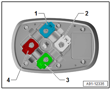
Roof Antenna -R216-
1 - GPS Antenna -R50-, blue
2 - Not assigned, white
3 - Satellite Antenna -R170-/Auxiliary Heater Antenna -R182-, green
4 - Telephone Antenna -R65-/LTE Antenna 2 -R306-, bordeaux