Audi A6 Typ 4G: Brake Booster/Brake Master Cylinder
Overview - Brake Booster/Brake Master Cylinder
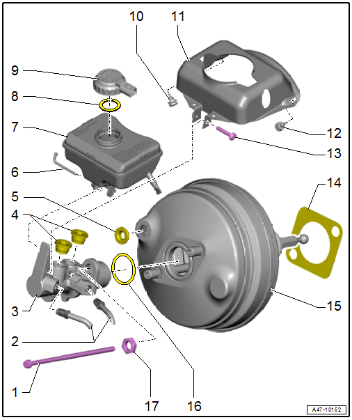
1 - Bolt
- 23 Nm
2 - Brake Lines
- 24 Nm
3 - Brake Master Cylinder
- Cannot be serviced. If malfunctioning, replace as complete unit.
- Removing and installing. Refer to → Chapter "Brake Master Cylinder, Removing and Installing".
4 - Sealing Plugs
- Coat with brake fluid and press into brake fluid reservoir
5 - Grommet
- For the vacuum line
- Insert in the brake booster
6 - Locking Pin
- Slide it through the brake fluid reservoir and the master brake cylinder.
- The locking pin must be pushed into the brake fluid reservoir tab.
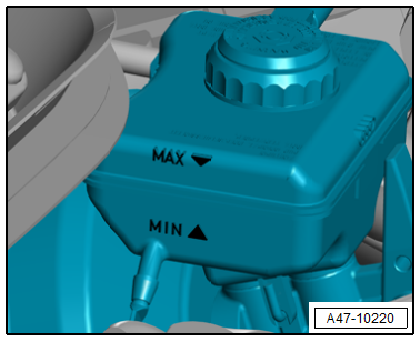
7 - Brake Fluid Reservoir
- Removing and installing. Refer to → Chapter "Brake Fluid Reservoir, Removing and Installing".
8 - Seal
9 - Cap
- With Brake Fluid Level Warning Switch -F34-
10 - Rubber Buffer
11 - Protective Plate
- Equipped on some models
12 - Rubber Buffer
13 - Bolt
- 8 Nm
14 - Gasket
- Replace after removing
15 - Brake Booster
- With adhesive seal
- If malfunctioning: replace as complete unit.
- Function Test:
- With the engine switched off, press the brake pedal firmly several times (to reduce the vacuum in the device).
- Hold the brake pedal with average foot pressure and start the engine. If the brake booster is working properly, the brake pedal will be felt to give noticeably under foot (booster becomes effective).
- Removing and installing. Refer to → Chapter "Brake Booster, Removing and Installing".
- Adjust the ball head. Refer to → Fig. "Adjusting the brake booster ball head".
16 - O-Ring
- Replace after removing
17 - Nut
- 49 Nm
- Self-locking
- Replace after removing
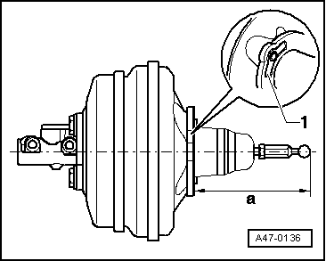
Adjusting the brake booster ball head
Dimension a = 164.7 mm +- 0.5 mm
 Note
Note
- Surface -1- for adjustment dimension.
- When measuring, ball head must be arranged at a right angle to the surface of the brake booster.
- Measure to end of ball head without the seal.
Tightening Specification
.png)
Brake Booster, Removing and Installing
Special tools and workshop equipment required
- Torque Wrench 1331 5-50Nm -VAG1331-
- M10 and M12 Plugs from the Assembly Part Set -5Q0698311-
 Caution
This procedure contains mandatory replaceable parts. Refer to component overview and parts catalog prior to starting procedure.
Mandatory Replacement Parts
- Gasket - Brake booster, mounting
Removing
- Turn off the engine.
- Push the brake pedal as many times as necessary until there is no more brake assistance.
- The brake pedal "becomes hard".
- Disconnect the brake pedal from the brake booster. Refer to → Chapter "Brake Pedal, Disconnecting from Brake Booster".
- Remove the plenum chamber bulkhead. Refer to → Body Exterior; Rep. Gr.50; Bulkhead; Overview - Bulkhead.
- Remove the brake fluid reservoir. Refer to → Chapter "Brake Fluid Reservoir, Removing and Installing".
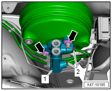
- Disconnect the connector -1- on the Brake Booster Pressure Sensor -G294-.
Caution
There is a Risk of damaging the vacuum hoses.
Carefully remove the vacuum hoses. A damaged vacuum hose must be replaced.
- Disconnect and remove the vacuum hose -1- from the brake booster.
- Place sufficient lint free clothes under the brake booster.
- Remove the brake lines -2-.
- Seal the open lines and connections with plugs from the Assembly Part Set -5Q0698311-.
- Remove the bolts -1- for the brake booster.
- Remove the brake booster with the brake master cylinder.
Installing
- Before installing brake booster, clean plenum chamber of remaining escaping brake fluid.
- When installing together the brake master cylinder and brake booster, make sure that the push rod is correctly located in the brake master cylinder.
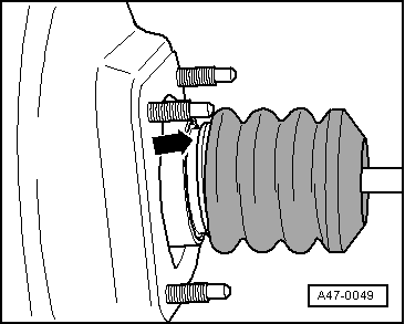
- Make sure that boot did not slip out of the circumferential groove, as shown here.
- Carefully install the brake booster in the guide and tighten.
- Tighten the bolts -1- for the brake booster.
- Insert the vacuum hose into the brake booster.
Caution
There is a Risk of damaging the vacuum hoses.
A damaged vacuum hose must be replaced.
- Insert the brake lines -2- into the master brake cylinder first and tighten them loosely.
- Tighten the brake lines -2-.
- Install the brake fluid reservoir. Refer to → Chapter "Brake Fluid Reservoir, Removing and Installing".
- Install the plenum chamber bulkhead. Refer to → Body Exterior; Rep. Gr.50; Bulkhead; Plenum Chamber Bulkhead, Removing and Installing.
- Attach the brake pedal to the brake booster. Refer to → Chapter "Brake Pedal, Attaching to Brake Booster".
Note
Make sure the ball head on the brake booster is installed correctly into the brake pedal mount.
- Bleed the brake system. Refer to → Chapter "Hydraulic System, Standard Bleeding".
 WARNING
Risk of accident!
Make sure the brakes are working correctly before driving the vehicle for the first time.
Brake Master Cylinder, Removing and Installing
Special tools and workshop equipment required
- Torque Wrench 1331 5-50Nm -VAG1331-
- M10 and M12 Plugs from the Assembly Part Set -5Q0698311-
Caution
This procedure contains mandatory replaceable parts. Refer to component overview and parts catalog prior to starting procedure.
Mandatory Replacement Parts
- Nuts - Brake master cylinder, mounting
- O-ring - Brake master cylinder to brake booster
Removing
WARNING
Health risks!
- Brake fluid is poisonous, and must never be siphoned by mouth under any circumstances.
- To prevent skin contact with brake fluid, wear chemical resistant safety gloves.
- Follow all disposal regulations.
Brake fluid contact with fluids containing mineral oils causes malfunctions.
Brake fluid must never come into contact with fluids containing mineral oils (oil, gas, cleaning solutions). Safety gloves must be free of oil and grease.
Risk of damaging the painted surfaces.
Due to its corrosive nature, brake fluid must also never contact paint. Wash off any spilled brake fluid immediately with plenty of water.
- Remove the brake fluid reservoir. Refer to → Chapter "Brake Fluid Reservoir, Removing and Installing".
Note
Place a cloth underneath to catch any brake fluid leaking out.
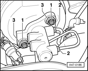
- Seal the open brake lines -2- with plugs from the Assembly Part Set -5Q0698311-.
- Remove the nuts -arrows-.
- Disconnect and remove the master brake cylinder -1- from the brake booster.
Installing
Install in reverse order of removal and note the following:
Note
Replace the seal after removal.
Caution
There is a risk of damaging the brake booster.
Do not let any brake fluid run into the brake booster.
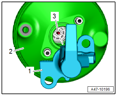
- When replacing the master brake cylinder -1- pay attention that the pressure rod -3- is seated correctly in the brake booster -2-.
- If necessary, have a second technician press the brake pedal slightly. This allows the brake master cylinder to be guided into pressure rod more easily.
- Install the brake fluid reservoir. Refer to → Chapter "Brake Fluid Reservoir, Removing and Installing".
WARNING
Risk of accident!
Make sure the brakes are working correctly before driving the vehicle for the first time.
Brake Fluid Reservoir, Removing and Installing
Special tools and workshop equipment required
- Torque Wrench 1331 5-50Nm -VAG1331-
- Brake Charger/Bleeder Unit -VAS5234-
- M10 and M12 Plugs from the Assembly Part Set -5Q0698311-
Removing
- Remove the tower brace. Refer to → Suspension, Wheels, Steering; Rep. Gr.40; Suspension Strut, Upper Control Arm; Tower Brace, Removing and Installing.
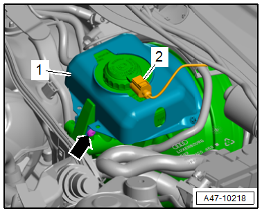
Vehicles with protective plate:
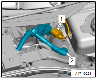
- Disconnect the connector -2- from the Brake Fluid Level Warning Switch -F34-.
- Remove the bolt -arrow- and remove the protective plate -1-.
Continuation for All Vehicles:
- Open the brake fluid reservoir.
Note
To prevent brake fluid from escaping, place enough lint-free cloths in the area under the brake master cylinder.
WARNING
Health risks!
- Brake fluid is poisonous, and must never be siphoned by mouth under any circumstances.
- To prevent skin contact with brake fluid, wear chemical resistant safety gloves.
- Follow all disposal regulations.
Brake fluid contact with fluids containing mineral oils causes malfunctions.
Brake fluid must never come into contact with fluids containing mineral oils (oil, gas, cleaning solutions). Safety gloves must be free of oil and grease.
Risk of damaging the painted surfaces.
Due to its corrosive nature, brake fluid must also never contact paint. Wash off any spilled brake fluid immediately with plenty of water.
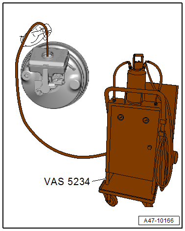
- Siphon as much brake fluid as possible using the Brake Charger/Bleeder Unit -VAS5234- and the Adapter -VAS5234/1- from the brake fluid reservoir.
- Remove the locking pin -1- for the brake fluid reservoir from the reservoir and the master brake cylinder.
- Pull out and remove the brake fluid reservoir -3-.
Note
- Brake fluid reservoir is engage in master brake cylinder on bottom side.
- Ignore -item 2-.
- Seal the open lines and connections with plugs from the Assembly Part Set -5Q0698311-.
Installing
Install in reverse order of removal and note the following:
- Coat the plugs on the brake fluid reservoir with brake fluid.
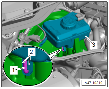
- Insert the brake fluid reservoir -3- into the plugs in the brake master cylinder.
- Slide the locking pin -1- through the brake fluid reservoir and the master brake cylinder until it engages in the retaining tabs -2-.
- Connect the connector to the Brake Fluid Level Warning Switch -F34-.
- If equipped install the protective plate.
- Fill the brake fluid to the "MIN" mark.
- Bleed the brake system. Refer to → Chapter "Hydraulic System, Standard Bleeding".
WARNING
Risk of accident!
Make sure the brakes are working correctly before driving the vehicle for the first time.