Audi A6 Typ 4G: Vacuum System
Check Valve, Checking
- Check valve is removed. Refer to → Chapter "Check Valve, Removing and Installing".
 Note
Note
The check valve is installed directly in front of the vacuum pump.
- Valve must allow air to flow in the direction of the arrow.
- Valve must remain closed in opposite direction.
- Observe the installation position.
- The flow direction arrow faces the vacuum pump.
Brake Booster Pressure Sensor, Removing and Installing
Removing
- Remove the cowl panel trim. Refer to → Body Exterior; Rep. Gr.50; Bulkhead; Plenum Chamber Cover, Removing and Installing.
- Disconnect the connector from the Brake Booster Pressure Sensor -G294--arrow-.
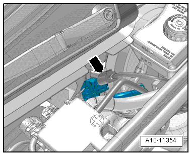
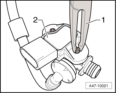
- Release clips with pliers -1-.
- Carefully pry out the Brake Booster Pressure Sensor -G294--item 2-.
Installing
Install in reverse order of removal and note the following:
- Install the cowl panel trim. Refer to → Body Exterior; Rep. Gr.50; Bulkhead; Plenum Chamber Cover, Removing and Installing.
Vacuum System, Checking
Tests and Test Requirements
Special tools and workshop equipment required
- Brake Servo Tester -VAS6721-
The following checks will be helpful when performing fault finding if there are complaints regarding the brake booster or the so-called "hard brake pedal".
The following components are included in the check:
- Brake Booster
- Gasket between the brake master cylinder and the brake booster
- Check Valve
- Vacuum hoses with connectors
- Vacuum pump (if equipped)
Keep the geographical surrounding in mind when evaluating the measurement results. The higher above sea level, the lower the air pressure.
Always observe all test requirements before checking the vacuum system:
- Visually inspect all of the vacuum hoses for damage (for example, tears or damage caused by animals) and secure fit
- Maintain clean working conditions when working on the vacuum system
- Clean the engine compartment before starting work, if necessary
Brake Booster Tester, Connecting
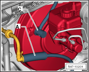
- Remove the vacuum hose from the brake booster.
Note
Pressing the brake pedal a few times beforehand makes it easier to remove the vacuum hose.
- Connect the Brake Servo Tester -VAS6721-.
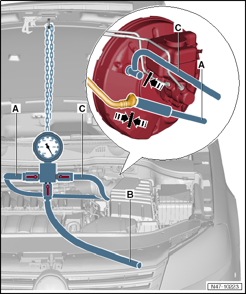
- Connect the hose -A- from the Brake Servo Tester -VAS6721- to the vacuum hose and push the adapter -C- into the brake booster.
Vacuum, Checking
Note
- The average earth atmospheric air pressure at sea level (N. N.) is 1013 mbar and it decreases dramatically at higher altitudes (approximately 100 mbar every 1000 meters higher) Local and time fluctuations also influence the vacuum.
- A cold engine, the A/C switched on as well as the engine simply idling can negatively influence the vacuum.
- Check all the vacuum hoses beforehand for damage (for example, tears or damage caused by animals) and secure fit.
- Connect the Brake Servo Tester -VAS6721-. Refer to → Chapter "Brake Booster Tester, Connecting".
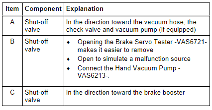
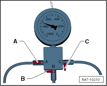
- Open the shut-off valve -A-.
- Close the shut-off valves -B and C-.
- Start the warm (above 60 ºC) engine and press the accelerator pedal one time quickly (engine speed higher than 2,000 RPM).
- Read the displayed measured value.
Normally (see note), the vacuum should be between 600 and 950 mbar (depending on the engine installed).
Check the vacuum system for leaks if the measured value is not reached, even though all requirements (see notes) are met.
- Create a vacuum using the Hand Vacuum Pump -VAS6213- for comparison. Refer to → Chapter "Vacuum, Creating with Hand Vacuum Pump".
Opening the shut-off valve -B- makes it easier to remove the hose connections and the adapter.
Leak Test
Note
- The average earth atmospheric air pressure at sea level (N. N.) is 1013 mbar and it decreases dramatically at higher altitudes (approximately 100 mbar every 1000 meters higher) Local and time fluctuations also influence the vacuum.
- A cold engine, the A/C switched on as well as the engine simply idling can negatively influence the vacuum.
- Check all the vacuum hoses beforehand for damage (for example, tears or damage caused by animals) and secure fit.
- Connect the Brake Servo Tester -VAS6721-. Refer to → Chapter "Brake Booster Tester, Connecting".
- Open the shut-off valve -A-.
- Close the shut-off valves -B and C-.
- Start the warm (above 60 ºC) engine and press the accelerator pedal one time quickly (engine speed higher than 2,000 RPM).
Normally (see note), the vacuum should be between 600 and 950 mbar (depending on the engine installed).
- Open the shut-off valve -C- to evacuate the brake booster.
- Turn off the engine.
- Read the displayed measured value and write it down.
- The vacuum may drop 400 mbar in 12 hours.
Note
The vacuum will drop considerably within a few seconds if there are large leaks.
- If the pressure drop is large, look for the area with the leak:
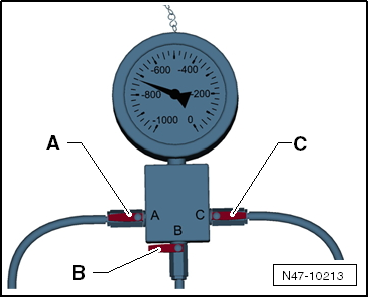
A - Testing the vacuum near the brake booster
- Close the shut-off valve -A- after creating the vacuum to test the brake booster vacuum system.
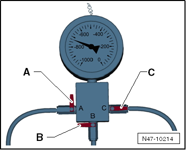
B - Testing the vacuum near the check valve, vacuum hoses with connectors and vacuum pump/intake manifold
- Close the shut-off valve -C- after creating the vacuum to check the vacuum system from the Brake Servo Tester -VAS6721- up to the intake manifold or up to the vacuum pump.
Opening the shut-off valve -B- makes it easier to remove the hose connections and the adapter.
Vacuum, Creating with Hand Vacuum Pump
Special tools and workshop equipment required
- Hand Vacuum Pump -VAS6213-
In certain situations, the vacuum can be created using a Hand Vacuum Pump -VAS6213- instead of using the engine or a vacuum pump.
- To do so, connect the Hand Vacuum Pump -VAS6213- to the vacuum hose from the connection -B- to the Brake Servo Tester -VAS6721-.
- Open the shut-off valve -B-.
- Create the vacuum using the Hand Vacuum Pump -VAS6213- until a vacuum between 600 and 950 mbar is displayed on the Brake Servo Tester -VAS6721-.
- Then perform the relevant tests.
