Audi A6 Typ 4G: Brake Inspection
General Information
- The operation takes place on a test stand.
- When testing, manual transmission vehicles must be in idle and automatic transmission vehicles must be in driving mode N.
- Always follow the instructions from the test stand manufacturer.
 Note
Note
Electronic brake control systems are inoperative when the ignition is switched off.
FWD Vehicles, Checking
- The brake inspection is to be performed on a one-axle roller test stand.
- The test speed must not exceed 5 km/h (3 mph), otherwise, the brakes may lock up due to the roller start-up delay (EDL regulation).
- Test stands approved by Audi meet these requirements.
AWD Vehicles, Checking
Testing on a one-axle roller test stand for AWD vehicles
- During this test, the wheels of one axle are driven in opposite directions, to prevent delivering power to the other axle.
- The test speed must not exceed 6 km/h (4 mph), otherwise the brakes may lock up due to the roller start-up delay (EDL regulation).
- Test stands approved by Audi meet these requirements.
Parking Brake, Checking
Test Sequence
- Drive in vehicle with rear wheels onto test rollers and do not switch off ignition.
Note
Do not switch off the ignition.
- As soon as the rollers reach a speed above 3 km/h (2 mph). the "TÜV mode" is activated.
- The yellow electromechanical parking brake symbol with a line through it appears in the instrument cluster. Refer to the Owner's Manual.
The electromechanical parking brake function is now:
- The brake does not close at once, but rather closes a bit each time the Electromechanical Parking Brake Button -E538- is pressed. The brake is completely closed in three stages.
- Pressing the Electromechanical Parking Brake Button -E538- releases the brakes again.
Prerequisite for "TÜV mode":
- Ignition is on
- Front wheels, speed = 0 km/ h (0 mph)
- Rear wheels, speed min. = 3, max. 9 km/h (6 mph).
 WARNING
A brake test stand with a regulated wheel set must be used on AWD vehicles.
Visual Characteristics of Ceramic Brake Rotors
Identifications on the ceramic brake rotor on the brake rotor cup
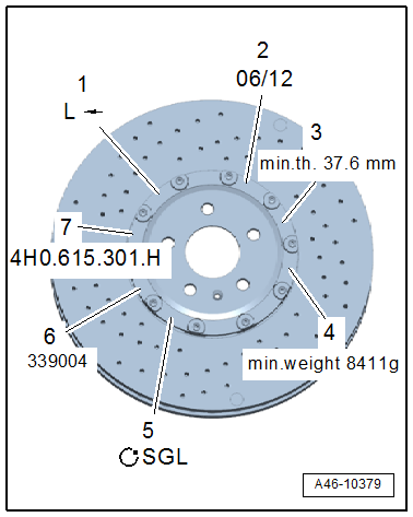
1 - Running Direction
2 - Brake Rotor Production Date
- Example
3 - Brake Rotor Minimum Thickness
- Example
- Wear limit
4 - Minimum Weight of Brake Rotor and Cup
- Example
5 - Supplier
- Example
6 - Brake Rotor Serial Production Number
- Example
7 - Audi Part Number
- Example
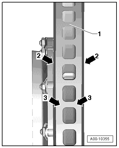
1 - Cooling Duct
2 - Friction Surface
3 - Base Material
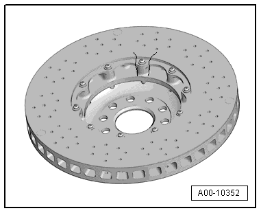
The friction surface on a new brake rotor already has stress cracks which occur during the production process. These stress cracks are all different.
Note
- Stress cracks do not mean the ceramic brake rotor is faulty.
- The stress cracks are somewhat visible and can be different from each other in strength.
- Check the connection area on the brake rotor ring and brake rotor cup. Refer to → Chapter "Cracks in Ceramic Brake Rotor Connection Area".
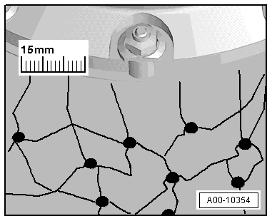
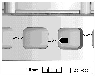
Surface Cracks in Cooling Duct Crosspieces
The cracks -arrow- on the surface of the cooling channels were produced during the manufacturing process.
Note
The surface cracks in the cooling duct crosspieces -arrow- do not mean the ceramic brake rotor is faulty.
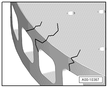
Cracks in Ceramic Brake Rotor Connection Area
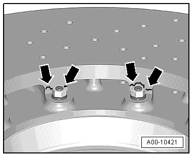
WARNING
Danger of an accident occurring if threaded connections are loose.
The brake rotor ring and the brake rotor cup are attached to each other and must never be separated. Never loosen the threaded connection on the brake rotor cup.
Ceramic brake rotors are to be replaced with the following types damage.
- Cracks near the threaded connectors on the cup leading to the connection area on the brake rotor -arrows -.
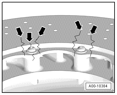
- Tangential cracks -arrows- in the connection area.
WARNING
If a brake rotor is damaged check the other brake rotors for damage and wear. Refer to → Chapter "Visual Characteristics of Ceramic Brake Rotors".
Chamfer
Chamfers -arrow- on the edges of the brake rotor are caused by mechanical damage.
The following are permitted:
- maximum width/depth = 2 mm.
- maximum length = 10 mm
- maximum number of chamfers on the brake rotor = 3
Ceramic brake rotors are to be replaced if any of these criteria are exceeded.
WARNING
If a brake rotor is damaged check the other brake rotors for damage and wear. Refer to → Chapter "Visual Characteristics of Ceramic Brake Rotors".
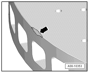
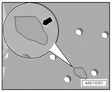
Nicks on Ceramic Brake Rotor
Ceramic brake rotors are to be replaced with the following types damage.
- Material break down on the friction surface greater than 1 cm -arrow-.
WARNING
If a brake rotor is damaged check the other brake rotors for damage and wear. Refer to → Chapter "Visual Characteristics of Ceramic Brake Rotors".
Crack in Cooling Channel
Ceramic brake rotors are to be replaced with the following types damage.
- Crack on the brake rotor friction surface leading to or through the cooling channel.
WARNING
If a brake rotor is damaged check the other brake rotors for damage and wear. Refer to → Chapter "Visual Characteristics of Ceramic Brake Rotors".