Audi A6 Typ 4G: Checking with Carbon-Ceramic Brake Wear Tester -VAS6813-
General Information, Carbon-Ceramic Brake Wear Tester -VAS6813-
 Note
Note
This is a new test procedure to determine the wear limit of the ceramic brake rotors
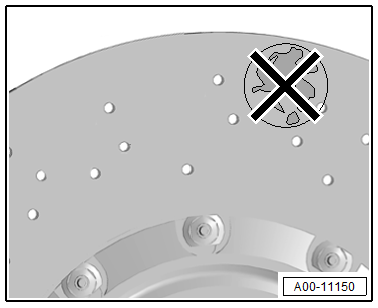
The brake rotor can be identified by the following points:
- the wear indicators -arrow- on the friction surface of the brake rotor are no longer present
- at the printed marks -A through D-
Note
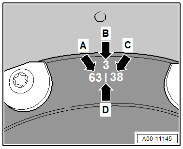
- The check occurs by determining the brake rotor thickness "and" the wear value with the Carbon-Ceramic Brake Wear Tester -VAS6813-, both must be measured three times respectively around the circumference.
- On the brake rotor cup the permitted minimum thickness "min.th" of the brake rotor is engraved.
- On the brake rotor cup the wear value -C- of the brake rotor for the Carbon-Ceramic Brake Wear Tester -VAS6813- is engraved.
- Value -A- is a value from the production of the new brake rotor
- The values -A and C- can be different depending on the location.
- The values -A and C- can be different depending on the brake rotor.
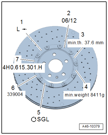
Example of min.th. -3-, brake rotor thickness. It must not fall short of this value.
Note
The value -3- can be different depending on the brake rotor.
General Information, Brake Rotor Wear
Note
- The check occurs by determining the brake rotor thickness "and" the wear value with the Carbon-Ceramic Brake Wear Tester -VAS6813-, both must be measured three times respectively around the circumference.
- The permitted minimum thickness of the brake rotor with "min.th" as well as the wear limit -C- for the Carbon-Ceramic Brake Wear Tester -VAS6813- are engraved on the brake rotor cup.
- The wear value -C- is different depending on the brake rotor and the measurement location.
Note
- If the brake rotor thickness "min.th." falls short at one measuring point the brake rotor must be replaced. Refer to → Chapter "Brake Rotor Thickness, Checking".
- "or"
- if during the check with the Carbon-Ceramic Brake Wear Tester -VAS6813- one of the three wear values -C- is reached or falls short the brake rotor must be replaced. Refer to → Chapter "Checking with Carbon-Ceramic Brake Wear Tester -VAS6813-".
Note
The wear value -C- is different depending on the brake rotor.
If there is abrasion both brake rotors on both sides of the axle must always be replaced.
Brake Rotor Thickness, Checking
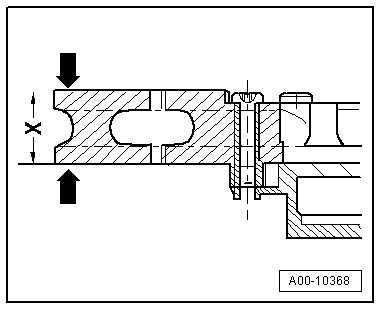
At a distance of 120º the marks for the measurement for deterring the wear can be found
Measure the brake rotor thickness at these three locations
here for example the third measuring point
The minimum permissible brake rotor thickness "min.th." is engraved in the brake rotor cup.
- Measure the brake rotor thickness -x- three times around the circumference at the measuring locations.
If the brake rotor thickness "min.th". falls short at one measuring point the brake rotor must be replaced.
Example of min.th. -3-, brake rotor thickness. It must not fall short of this value.
Note
The value -3- can be different depending on the brake rotor.
If there is abrasion both brake rotors on both sides of the axle must always be replaced.
If the brake rotor thickness does "not" fall short continue. Refer to → Chapter "Checking with Carbon-Ceramic Brake Wear Tester -VAS6813-".
Carbon-Ceramic Brake Wear Tester -VAS6813-, Checking
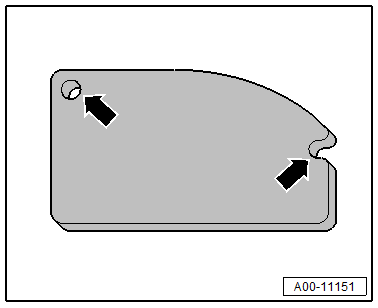
"Before" the measurement the Carbon-Ceramic Brake Wear Tester -VAS6813- must be checked using the supplied measurement plate.
Measurement plate:
- Place the measuring device in both openings of the measurement plate, -arrows- so that the laser beam points under the mark with the attached reference value.
- Switch on the measuring device.
The value displayed on the display must correspond to the reference value attached to the measurement plate.
Note
- If the difference to the reference value is more than +- 2.0 units the measuring device must be calibrated by a specialist company.
- For more information refer to the supplied Owner's Manual.
Checking with Carbon-Ceramic Brake Wear Tester -VAS6813-
Special tools and workshop equipment required
- Carbon-Ceramic Brake Wear Tester -VAS6813-
Note
- The check occurs by determining the brake rotor thickness "and" the wear value with the Carbon-Ceramic Brake Wear Tester -VAS6813-, both must be measured three times respectively around the circumference.
- The wear value -C- for the Carbon-Ceramic Brake Wear Tester -VAS6813- is engraved on the brake rotor cup.
- The values -A and C- can be different depending on the location.
- The values -A and C- can be different depending on the brake rotor.
- Value -A- is a value from the production of the new brake rotor
- The wheel is installed.
- The brake rotor thickness is checked.
- The measuring device is checked. Refer to → Chapter "Carbon-Ceramic Brake Wear Tester -VAS6813-, Checking".
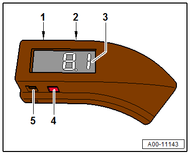
Carbon-Ceramic Brake Wear Tester -VAS6813-:
- 1 On/Off button
- 2 Measured value hold button
- 3 Measured value display
- 4 Laser beam positioning tab
- 5 Interface
Note
For additional information on the Carbon-Ceramic Brake Wear Tester -VAS6813- refer to the supplied Owner's Manual.
Measurement:
- The brake rotor must be clean.
- The brake rotor must be dry.
 WARNING
Health Risk.
- Always wear a mouth and nose mask when using compressed air to clean the ceramic brake rotor.
- Never clean the brake rotor with water or any other fluid.
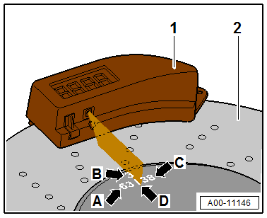
At a distance of 120º the marks for the measurement for deterring the wear can be found
The following described measurement must take place on all three measurement locations to guarantee a correct check.
-A- new value, -C- wear value, -B- number of the measurement location, -D- mark for the laser beam for the measurement of the wear value.
For example the third measurement location -B- from "1 to 3" can be seen.
Note
- The values -A and C- are different depending on the location.
- The values -A and C- are different depending on the brake rotor.
- Place the Carbon-Ceramic Brake Wear Tester -VAS6813- flush on the outer edge of the brake rotor.
- Switch on the Carbon-Ceramic Brake Wear Tester -VAS6813-.
- Move the Carbon-Ceramic Brake Wear Tester -VAS6813--1- along the outer edge -2- until the laser beam points exactly on the mark -D- on the brake rotor.
- Determine the wear on all three measurement locations of the brake rotor from "1 to 3".
- Read the displayed value on the Carbon-Ceramic Brake Wear Tester -VAS6813-
If one of the three wear values -C- is reached or falls short, the brake rotor must be removed for further checking.
Note
The wear value -C- is different depending on the measurement location.
- Remove the brake rotor.
Note
- To avoid false measurement, place the brake rotor on a non-electrically conductive surface (for example a wooden table).
- The surface must be clean and dry
- The brake rotor must be clean and dry
- Place the Carbon-Ceramic Brake Wear Tester -VAS6813- again flush on the outer edge of the brake rotor.
The measurement must take place again on all three measurement locations to guarantee a correct check.
- Move the Carbon-Ceramic Brake Wear Tester -VAS6813--1- back along the outer edge -2- until the laser beam points exactly on the mark -D- on the brake rotor.
- Determine the wear on all three measurement locations of the brake rotor from "1 to 3".
- Read the displayed value on the Carbon-Ceramic Brake Wear Tester -VAS6813-.
If one of the three wear values -C- is reached or falls short the brake rotor must be replaced.
If there is abrasion both brake rotors on both sides of the axle must always be replaced.
Special Tools
Special tools and workshop equipment required
- Battery Charger -VAS5095A-
- Carbon-Ceramic Brake Wear Tester -VAS6813-
