Audi A6 Typ 4G: Brake Pad Wear Indicator Wire, Removing and Installing
Brake Pad Wear Indicator Wire, Removing and Installing, Steel Brakes, 1LA/1LJ
Removing
- Remove the affected front wheel. Refer to → Suspension, Wheels, Steering; Rep. Gr.44; Wheels, Tires.
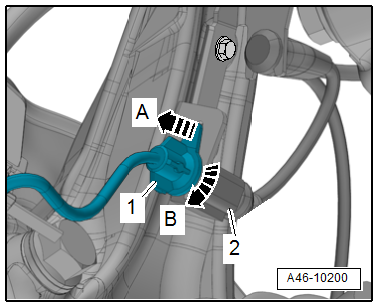
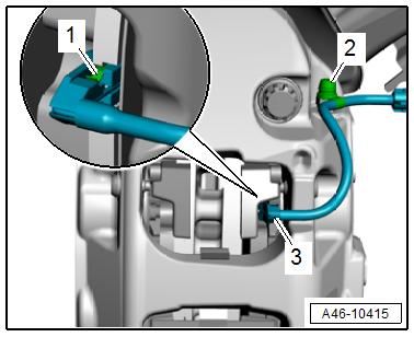
- Disconnect the connector -2- from the brake pad wear indicator.
- Release the connector -1- to the brake pad wear sensor from the bracket -arrow A- and turn it 90º at the same time -arrow B-.
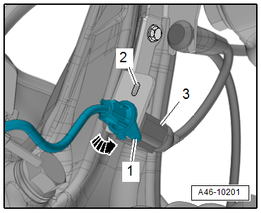
- Free up the wire for the brake pad wear sensor, to do so open the dust cap -3- and disengage the wire from the brake caliper arrows.
- Remove the contact -1- for the brake pad wear sensor from the brake pad, while being careful of the clips -2-.
 Note
Note
If the clips -2- go missing, the brake pad wear sensor must be replaced.
Installing
- Insert the contact -1- for the brake pad wear sensor with the clip -2- into the brake pad until it engages.
Note
Make sure that the brake pad wear sensor contact sits correctly in the brake pad.
- Secure the wire for the brake pad wear sensor with the dust cap -3- and engage on the brake caliper as shown.
- Bring the connector into the installation position and turn in the direction of the -arrow- until the tab -1- engages in the opening -2- on the bracket.
- Connect the connector -3-.
- Install the front wheel. Refer to → Suspension, Wheels, Steering; Rep. Gr.44; Wheels, Tires.
Brake Pad Wear Indicator Wire, Removing and Installing, Steel Brakes, 1LF/1LL
Removing
- Remove the affected front wheel. Refer to → Suspension, Wheels, Steering; Rep. Gr.44; Wheels, Tires.
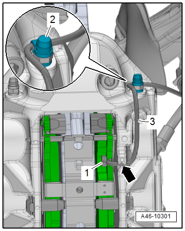
- Disconnect the brake pad wear sensor connector -2-.
- Release the connector -1- to the brake pad wear sensor from the bracket -arrow A- and turn it 90º at the same time -arrow B-.
- Remove the contact -1- for the brake pad wear sensor from the brake pad, while being careful of the clips -2-.
- Free up the wire from the brake hose -3- and the bracket -4-.
Note
If the clips -2- go missing, the brake pad wear sensor must be replaced.
Installing
Install in reverse order of removal and note the following:
Note
- Check the contact for the brake pad wear sensor for damage, replacing if necessary.
- Make sure that the brake pad wear sensor contact sits correctly in the brake pad.
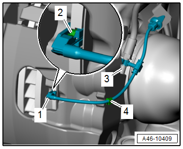
- Press the contact -1- for the brake pad wear sensor with the clip -2- into the inner brake pad until it engages.
- Engage the wire at the bracket -4- and the brake hose -3-.
- Bring the connector into the installation position and turn in the direction of the -arrow- until the tab -1- engages in the opening -2- on the bracket.
- Connect the connector -3-.
- Install the front wheel. Refer to → Suspension, Wheels, Steering; Rep. Gr.44; Wheels, Tires.
Brake Pad Wear Indicator Wire, Removing and Installing, Steel Brakes, 1LU
Removing
- Remove the affected front wheel. Refer to → Suspension, Wheels, Steering; Rep. Gr.44; Wheels, Tires.
- Disconnect the connector -2- from the brake pad wear indicator.
- Release the connector -1- to the brake pad wear sensor from the bracket -arrow A- and turn it 90º at the same time -arrow B-.
- Free up the wire for the brake pad wear sensor by opening the dust cap -2-.
- Remove the contact -3- for the brake pad wear sensor from the brake pad, while being careful of the clamps -1-.
Note
If the clamps -1- go missing, the brake pad wear sensor must be replaced.
Installing
- Insert the contact -3- for the brake pad wear sensor into the brake pad until it engages.
Note
Make sure that the brake pad wear sensor contact sits correctly in the brake pad.
- Secure the wire for the brake pad wear sensor with the dust cap -2- as shown.
- Bring the connector into the installation position and turn in the direction of the -arrow- until the tab -1- engages in the opening -2- on the bracket.
- Connect the connector -3-.
- Install the front wheel. Refer to → Suspension, Wheels, Steering; Rep. Gr.44; Wheels, Tires.
Brake Pad Wear Indicator Wire, Removing and Installing, Steel Brakes, 1LM/1LX
Note
The brake pad wear sensor cannot be removed without damaging it.
Removing
- Remove the affected front wheel. Refer to → Suspension, Wheels, Steering; Rep. Gr.44; Wheels, Tires.
- Disconnect the brake pad wear sensor connector -2-.
- Release the connector -1- to the brake pad wear sensor from the bracket -arrow A- and turn it 90º at the same time -arrow B-.
- Free up the brake pad wear sensor electrical wire -3- by opening the dust cap -2- and unclip it from the brake caliper -arrow-.
- Remove the brake pad wear sensor contact -1- from the brake pad with pliers.
Installing
- Insert the brake pad wear sensor contact -1- in the brake pad until it engages.
Note
Make sure that the brake pad wear sensor contact fits correctly in the brake pad.
- Secure the brake pad wear sensor electrical wire -3- by guiding it on the brake caliper -arrow- and securing it with the dust cap -2- as illustrated.
- Bring the connector into its installed position and turn in the direction of the -arrow- until the tab -1- engages in the hole -2- on the bracket.
- Connect the connector -3-.
- Install the front wheel. Refer to → Suspension, Wheels, Steering; Rep. Gr.44; Wheels, Tires.
Brake Pad Wear Indicator Wire, Removing and Installing, Ceramic Brakes, 1LN/1LW
Note
The brake pad wear sensor cannot be removed without damaging it.
Removing
- Remove the affected front wheel, while observing the safety precautions for vehicles with ceramic brakes. Refer to → Suspension, Wheels and Steering; Rep. Gr.44; Wheels, Tires.
- Disconnect the connector -2- from the brake pad wear indicator.
- Release the connector -1- to the brake pad wear sensor from the bracket -arrow A- and turn it 90º at the same time -arrow B-.
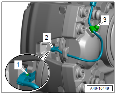
- Free up the brake pad wear sensor electrical wire -1- by opening the dust cap -3- and guiding it out from the bracket -2- and brake caliper -arrow-.
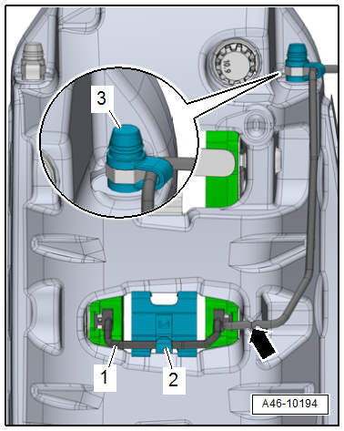
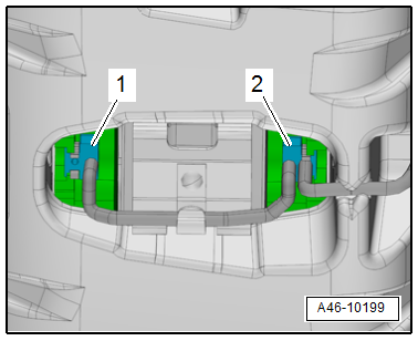
- Remove the brake pad wear sensor contacts -1 and 2- from the brake pads with pliers.
Installing
- Insert the brake pad wear sensor contacts -1 and 2- in the brake pads until they engage.
- The unattached wire connection faces toward the vehicle interior.
Note
Make sure that the brake pad wear sensor contacts fit correctly in the brake pads.
- To secure the brake pad wear sensor electrical wire -1-, attach the wire at the bracket -2-, route it through the brake caliper -arrow-, and secure it with the dust cap -3- as illustrated.
- Bring the connector into its installed position and turn in the direction of the -arrow- until the tab -1- engages in the hole -2- on the bracket.
- Connect the connector -3-.
- Install the front wheel, while observing the safety precautions for vehicles with ceramic brakes. Refer to → Suspension, Wheels and Steering; Rep. Gr.44; Wheels, Tires.
