Audi A6 Typ 4G: Overview - Rear Brakes
Overview - Rear Brakes, Steel Brakes
 Note
Note
Applies to all steel rear brakes
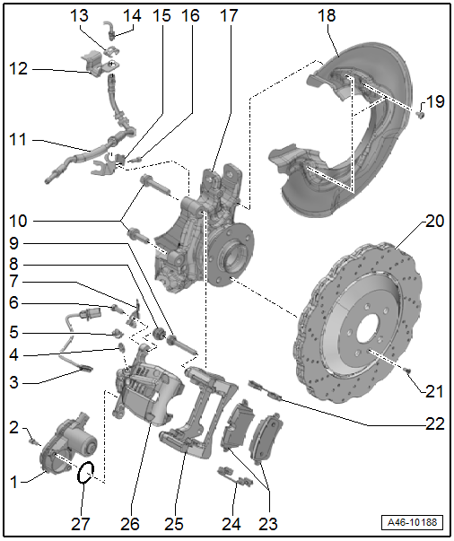
1 - Electromechanical Parking Brake Motor
- Left Parking Brake Motor -V282-/Right Parking Brake Motor -V283-
- Left Parking Brake Motor -V282-/Right Parking Brake Motor -V283-, removing and installing. Refer to → Chapter "Left/Right Parking Brake Motor -V282-/-V283-, Removing and Installing".
- Electromechanical Parking Brake Control Module -J540-, removing and installing. Refer to → Chapter "Electromechanical Parking Brake Control Module -J540-, Removing and Installing".
2 - Bolts
- 12 Nm
3 - Brake Pad Wear Sensor
- Left Rear Brake Pad Wear Sensor -G36-/Right Rear Brake Pad Wear Sensor -G37-
- For inner brake pad
- Replace if damaged
- Cannot be removed without being damaged
- Removing and installing. Refer to → Chapter "Brake Pad Wear Indicator Wire, Removing and Installing, Steel Brakes".
4 - Bleed Screw
- 13 Nm
- Bleed the brake system. Refer to → Chapter "Hydraulic System, Standard Bleeding".
5 - Protective Cap
6 - Bolt
- 35 Nm
- Self-locking
- Replace after removing
- When loosening and tightening, counterhold at the guide pin
7 - Bracket
- For the connector
8 - Protective Cover
- For the guide pins
- Install the repair kit if the caps or guide pins are damaged. Use the supplied grease packet to lubricate guide pins
9 - Guide Pin
- Check ease of movement
- Install the repair kit if the caps or guide pins are damaged. Use the supplied grease packet to lubricate guide pins
10 - Bolt
- 100 Nm +90º
- With a washer
- Note the different bolt lengths. The long bolt sits above.
- Replace after removing
11 - Brake Hose
- Make sure the brake hose is routed correctly. Make sure the brake hose is not blocked, bent or rubbing against the vehicle.
- Replace if damaged
- Make sure that tabs are properly seated in the grooves on the bracket.
- 20 Nm (brake hose to brake caliper)
12 - Bracket
- For brake hose
- Welded onto the body
13 - Spring
- Replace if damaged
14 - Brake Line
- 14 Nm (brake line to brake hose)
15 - Bracket
- For brake hose and electrical wires
16 - Bolt
- 9 Nm
17 - Stub Axle Carrier
18 - Brake Shield
- Removing and installing. Refer to → Chapter "Brake Shield, Removing and Installing".
19 - Bolt
- 10 Nm
20 - Brake Rotor
- Allocation. Refer to the Parts Catalog.
- Wear limit. Refer to → Chapter "Technical Data, Brakes"
- Always replace on both sides of the axle
- Removing and installing. Refer to → Chapter "Brake Rotor, Removing and Installing, Steel Brakes".
21 - Bolt
- 10 Nm
22 - Brake Pad Spring
- Replace when pads are replaced
- Make sure it fits correctly in the brake carrier
23 - Brake Pads
- Allocation. Refer to the Parts Catalog.
- Checking pad thickness. Refer to → for the wear limit.
- Always replace on both sides of the axle
- Removing and installing. Refer to → Chapter "Brake Pads, Removing and Installing, Steel Brakes".
- Note installation position:
- Identification "BA" = outer brake pad
- Identification "BI" = inner brake pad with brake pad wear indicator mount
24 - Brake Pad Spring
- Replace when pads are replaced
- Make sure it fits correctly in the brake carrier
25 - Brake Carrier
- Delivered as an assembled replacement part with sufficient grease on the guide pins
- Install the repair kit if the caps or guide pins are damaged. Use the supplied grease packet to lubricate guide pins
26 - Brake Caliper
- Removing and installing. Refer to → Chapter "Brake Caliper, Removing and Installing, Steel Brakes".
- Replacing. Refer to → Chapter "Brake Caliper, Replacing, Steel Brakes".
- Servicing. Refer to → Chapter "Brake Caliper Piston, Removing and Installing".
27 - O-Ring
- Replace after removing
Overview - Rear Brakes, Ceramic Brakes
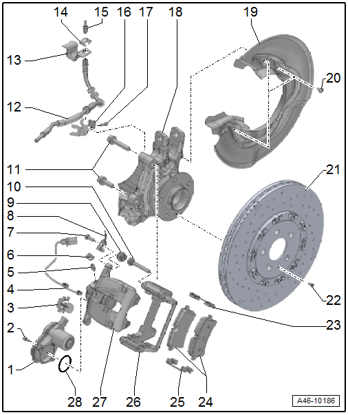
1 - Electromechanical Parking Brake Motor
- Left Parking Brake Motor -V282-/Right Parking Brake Motor -V283-
- Left Parking Brake Motor -V282-/Right Parking Brake Motor -V283-, removing and installing. Refer to → Chapter "Left/Right Parking Brake Motor -V282-/-V283-, Removing and Installing".
- Electromechanical Parking Brake Control Module -J540-, removing and installing. Refer to → Chapter "Electromechanical Parking Brake Control Module -J540-, Removing and Installing".
2 - Bolts
- 12 Nm
3 - Bracket
- For brake pad wear sensor electrical wire
4 - Brake Pad Wear Sensor
- Left Rear Brake Pad Wear Sensor -G36-/Right Rear Brake Pad Wear Sensor - G37-
- Replace if damaged
- Cannot be removed without damaging it
- Removing and installing. Refer to → Chapter "Brake Pad Wear Indicator Wire, Removing and Installing, Ceramic Brakes".
5 - Bleed Screw
- 13 Nm
- Bleed the brake system. Refer to → Chapter "Hydraulic System, Standard Bleeding".
6 - Protective Cap
7 - Bolt
- 35 Nm
- Self-locking
- Replace after removing
- When loosening and tightening, counter-holding the guide pin
8 - Bracket
- For the connector
9 - Protective Cover
- For the guide pins
- Install the repair kit if the caps or guide pins are damaged. Use the supplied grease packet to lubricate the guide pins.
10 - Guide Pin
- Check ease of movement
- Install the repair kit if the caps or guide pins are damaged. Use the supplied grease packet to lubricate the guide pins.
11 - Bolt
- 100 Nm +90º
- With a washer
- Note the different bolt lengths. The long bolt sits above.
- Replace after removing
- When loosening and tightening, counter-holding the guide pin
12 - Brake Hose
- Make sure the brake hose is routed correctly. Make sure the brake hose is not blocked, bent or rubbing against the vehicle.
- Replace if damaged
- Make sure that tabs are properly seated in the grooves on the bracket.
- 20 Nm (brake hose to brake caliper)
13 - Bracket
- For brake hose
- Welded onto the body
14 - Spring
- Replace if damaged
15 - Brake Line
- 14 Nm (brake line to brake hose)
16 - Bracket
- For brake hose and electrical wires
17 - Bolt
- 9 Nm
18 - Stub Axle Carrier
19 - Brake Shield
- Removing and installing. Refer to → Chapter "Brake Shield, Removing and Installing".
20 - Bolt
- 10 Nm
21 - Brake Rotor
- Allocation. Refer to the Parts Catalog.
- Brake Rotor Thickness. Refer to → Chapter "Ceramic Brake Rotor, Determining Wear".
- Additionally check for:
- Cracks in connection area. Refer to → Chapter "Cracks in Ceramic Brake Rotor Connection Area".
- Chamfer. Refer to → Chapter "Chamfer".
- Nicks. Refer to → Chapter "Nicks on Ceramic Brake Rotor".
- Crack in cooling channel. Refer to → Chapter "Crack in Cooling Channel".
- Brake Rotor Thickness. Refer to → Chapter "Ceramic Brake Rotor, Determining Wear".
- Always replace on both sides of the axle
- Removing and installing. Refer to → Chapter "Brake Rotor, Removing and Installing, Ceramic Brakes".
22 - Bolt
- 10 Nm
23 - Brake Pad Spring
- Replace when pads are replaced
- Make sure it fits correctly in the brake carrier
24 - Brake Pads
- Checking pad thickness. Refer to → for the wear limit.
- Always replace on both sides of the axle
- Allocation. Refer to the Parts Catalog.
- Removing and installing. Refer to → Chapter "Brake Pads, Removing and Installing, Ceramic Brakes".
25 - Brake Pad Spring
- Replace when pads are replaced.
- Make sure it fits correctly in the brake carrier.
26 - Brake Carrier
- Delivered as an assembled replacement part with sufficient grease on the guide pins
- Install the repair kit if the caps or guide pins are damaged. Use the supplied grease packet to lubricate guide pins
27 - Brake Caliper
- Removing and installing. Refer to → Chapter "Brake Caliper, Removing and Installing, Ceramic Brakes".
- Replacing. Refer to → Chapter "Brake Caliper, Replacing, Ceramic Brakes".
- Servicing. Refer to → Chapter "Brake Caliper Piston, Removing and Installing".
28 - O-Ring
- Replace after removing
