Audi A6 Typ 4G: Electronic Damping
Component Location Overview - Electronic Damping
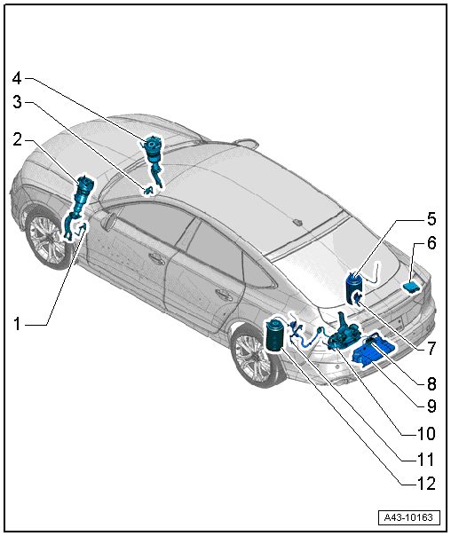
1 - Left Front Level Control System Sensor -G78-
- Removing and installing. Refer to → Chapter "Left/Right Front Level Control System Sensor -G78-/-G289-, Removing and Installing".
- After loosening, adapt the control position. Refer to → Chapter "Control Position, Programming".
- Test using a Vehicle Diagnostic Tester in Guided Fault Finding
2 - Left Front Air Spring
- With Left Front Damping Adjustment Valve -N336-
- Removing and installing. Refer to → Chapter "Spring, Removing and Installing, Air Spring".
- Filling. Refer to → Chapter "System, Venting or Filling".
3 - Right Front Level Control Sensor -G289-
- Removing and installing. Refer to → Chapter "Left/Right Front Level Control System Sensor -G78-/-G289-, Removing and Installing".
- After loosening, adapt the control position. Refer to → Chapter "Control Position, Programming".
- Test using a Vehicle Diagnostic Tester in Guided Fault Finding
4 - Right Front Air Spring
- With Right Front Damping Adjustment Valve -N337-
- Removing and installing. Refer to → Chapter "Spring, Removing and Installing, Air Spring".
- Filling. Refer to → Chapter "System, Venting or Filling".
5 - Rear Right Air Spring
- Removing and installing. Refer to → Chapter "Shock Absorber, Removing and Installing".
- Filling. Refer to → Chapter "System, Venting or Filling".
6 - Level Control System Control Module -J197-
- Removing and installing. Refer to → Chapter "Level Control System Control Module -J197-, Removing and Installing".
- Allocation. Refer to the Parts Catalog.
7 - Right Rear Level Control System Sensor -G77-
- Removing and installing. Refer to → Chapter "Left/Right Rear Level Control System Sensor -G76-/-G77-, Removing and Installing".
- After loosening, adapt the control position. Refer to → Chapter "Control Position, Programming".
- Test using a Vehicle Diagnostic Tester in Guided Fault Finding
8 - Solenoid Valve Block
- Removing and installing. Refer to → Chapter "Solenoid Valve Block, Removing and Installing"
9 - Pressure Reservoir
- Removing and installing. Refer to → Chapter "Pressure Reservoir, Removing and Installing".
10 - Air Supply Unit
- Overview. Refer to → Chapter "Overview - Air Supply Unit"
- If the air supply unit was replaced, then the Level Control System Compressor Relay -J403- must also be replaced. Installed location. Refer to → Wiring diagrams, Troubleshooting & Component locations
11 - Left Rear Level Control System Sensor -G76-
- Removing and installing. Refer to → Chapter "Left/Right Rear Level Control System Sensor -G76-/-G77-, Removing and Installing".
- After loosening, adapt the control position. Refer to → Chapter "Control Position, Programming".
- Test using a Vehicle Diagnostic Tester in Guided Fault Finding
12 - Rear Left Air Spring
- Removing and installing. Refer to → Chapter "Shock Absorber, Removing and Installing".
- Filling. Refer to → Chapter "System, Venting or Filling".
Control Position, Programming
 Note
Note
Adapting control position and checking headlamp basic setting is necessary if:
- The lower transverse link has been removed and reinstalled or replaced
- The subframe was replaced,
- Installation work has been performed on the level control system sensor,
- The level control system sensor has been replaced,
- The level control system sensor coupling rod threaded connection was loosened at the lower transverse link.
- The Level Control System Control Module -J197- was replaced.
Requirements
- The vehicle must be standing on an even surface.
- The vehicle may not be loaded.
The programing and control position is performed using the Vehicle Diagnostic Tester:
VAS PC
Connect Vehicle Diagnostic Tester.
- Select Guided Functions mode.
- Select the "34 - Level Control System Control Module" address.
- Select "J197 - reprogram control position" and follow the instructions on the screen.
ODIS - Offboard Diagnostic Information System
Connect Vehicle Diagnostic Tester.
- Select Diagnostic operating mode and start diagnostics.
- Select the Control Module tab.
- Select the "34 - Level Control System Control Module" address.
- Select "J197 - reprogram control position" and follow the instructions on the screen.
Note
- If the control position was reprogrammed and if the vehicle has lane assist, then it will then be necessary to recalibrate the Camera Control Module -J852-. Refer to → Chapter "Driver Assistance Systems Front Camera, Calibrating".
- Perform the basic setting of the headlamps. Refer to → Electrical Equipment; Rep. Gr.94; Headlamp; Headlamp, Adjusting.
System, Venting or Filling
The bleeding/filling of the air suspension system is performed using the Vehicle Diagnostic Tester.
VAS PC
Connect Vehicle Diagnostic Tester.
- Select Guided Functions mode.
- Select the "34 - Level Control System Control Module" address.
- Select "J197 - venting or filling the system" and follow the instructions on the screen.
ODIS - Offboard Diagnostic Information System
Connect Vehicle Diagnostic Tester.
- Select Diagnostic operating mode and start diagnostics.
- Select the Control Module tab.
- Select the "34 - Level Control System Control Module" address.
- Select "J197 - venting or filling the system" and follow the instructions on the screen.
