Audi A6 Typ 4G: Level Control System Sensor
Overview - Level Control System Sensor
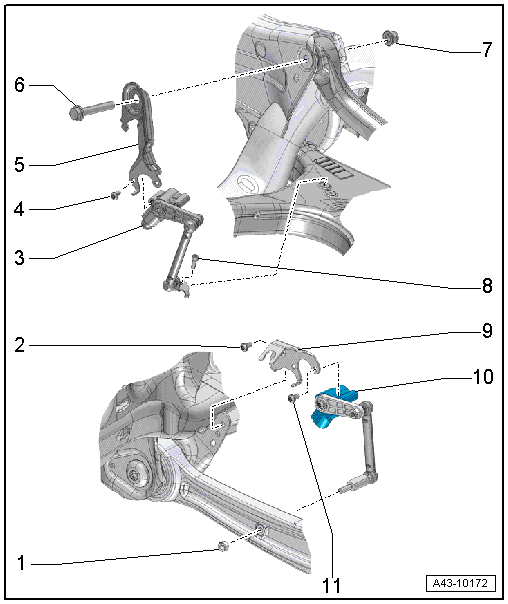
1 - Nut
- 9 Nm
- Self-locking
- Replacing
2 - Bolt
- 9 Nm
3 - Rear Level Control System Sensor
- Left side Left Rear Level Control System Sensor -G76-
- Right side Right Rear Level Control System Sensor -G77-
- Removing and installing. Refer to → Chapter "Left/Right Rear Level Control System Sensor -G76-/-G77-, Removing and Installing".
4 - Bolt
- 5 Nm
5 - Bracket
- For the rear vehicle level sensor
6 - Bolt
- Tightening specification -Item 8-.
7 - Nut
- Always replace if removed
8 - Bolt
- 9 Nm
9 - Bracket
- For the front vehicle level sensor
10 - Front Vehicle Level Sensor
- Left side Left Front Level Control System Sensor -G78-
- Right side Right Front Level Control Sensor -G289-
- Removing and installing. Refer to → Chapter "Left/Right Front Level Control System Sensor -G78-/-G289-, Removing and Installing".
11 - Bolt
- 5 Nm
General Information
Vehicles with level control and/or HID headlamps have standard automatic headlamp range control. Refer to → Electrical Equipment; Rep. Gr.94; Automatic Headlamp Range Control; Overview - Automatic Head Lamp Range Control.
To function properly, the level control and automatic headlamp range control system need information about compression travel or rebound travel at the front and rear axles.
For this, the position of the left/right lower transverse link in relation to the body is transferred via a coupling rod to Left Rear Level Control System Sensor -G76- and Right Rear Level Control System Sensor -G77-. They transmit electrical signals to the Level Control System Control Module -J197-.
The signals from the Left Front Level Control System Sensor -G78- and the Right Front Level Control Sensor -G289- are transmitted to the Level Control System Control Module -J197- at the rear axle.
These signals are required for determining vehicle level.
The headlamp range control responds automatically to changes in the vehicle level.
The vehicle level can change in the following situations:
- Trailer Mode
- Different load conditions; vehicle empty, vehicle partially or fully loaded
 Note
Note
Adapting control position and checking headlamp basic setting is necessary if
- The lower transverse link has been removed and reinstalled or replaced
- The subframe was replaced,
- Installation work has been performed on the level control system sensor,
- The level control system sensor has been replaced,
- The Level Control System Sensor coupling rod threaded connection was loosened at the lower transverse link.
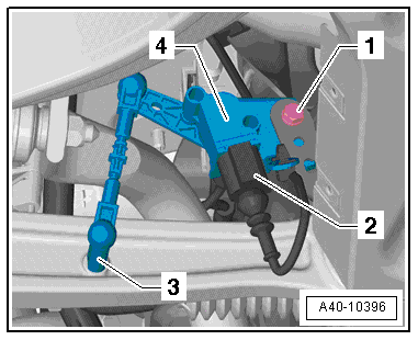
Left/Right Front Level Control System Sensor -G78-/-G289-, Removing and Installing
Special tools and workshop equipment required
- Torque Wrench 1410 -VAG1410-
Removing
- Disconnect connector -2-.
- Remove the nut (not illustrated) from the mount -3-.
- Remove the bolt -1-.
- Remove the level control system sensor -4-.
Installing
Install in reverse order of removal. Note the following:
- Sensor lever must point toward front.
- Guide the retaining hook on the sensor bracket into the subframe.
- Adapt the control position. Refer to → Chapter "Control Position, Programming".
- Perform the basic setting of the headlamps. Refer to → Electrical Equipment; Rep. Gr.94; Headlamp; Headlamp, Adjusting.
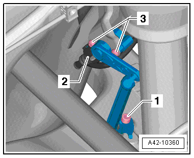
Left/Right Rear Level Control System Sensor -G76-/-G77-, Removing and Installing
Special tools and workshop equipment required
- Torque Wrench 1410 -VAG1410-
Removing
- Disconnect the connector -2-.
- Remove the bolt -1- from the coupling rod.
- Remove the bolts -3- and the vehicle level sensor.
Installing
Install in reverse order of removal. Note the following:
- Sensor lever must point toward front.
- Adapt the control position. Refer to → Chapter "Control Position, Programming".
- Perform the basic setting of the headlamps. Refer to → Electrical Equipment; Rep. Gr.94; Headlamp; Headlamp, Adjusting.